HEADUP DISPLAY DISASSEMBLY
CAUTION / NOTICE / HINT
Note
When disassembling the headup display, eliminate static electricity by touching the vehicle body to prevent components from being damaged.
PROCEDURE
-
REMOVE COMBINATION METER MIRROR GLASS
-
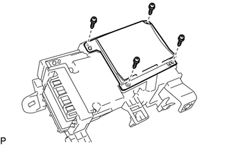
Remove the 4 screws and combination meter mirror glass.
-
-
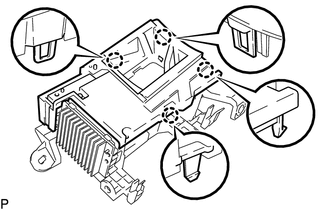
REMOVE METER CIRCUIT PLATE COVER
-
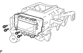
Remove the 4 screws.
-
Disengage the guide to remove the meter circuit plate cover as shown in the illustration.
-
-
REMOVE NO. 1 COMBINATION METER MIRROR CASE
-
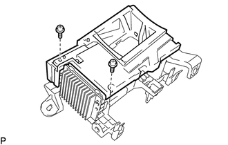
Remove the 2 screws.
-
Disengage the 4 claws and remove the No. 1 combination meter mirror case.
-
-
REMOVE COMBINATION METER MIRROR
-
Disconnect the connector.
-
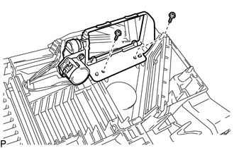
Remove the 2 screws and combination meter mirror.
-
-
REMOVE NO. 1 COMBINATION METER MIRROR PLATE
-
Disengage the 2 claws and remove the No. 1 combination meter mirror plate as shown in the illustration.
-
-
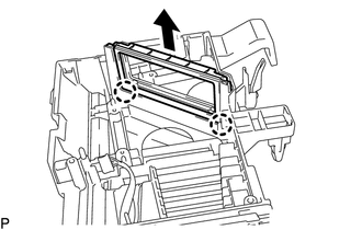
REMOVE NO. 2 COMBINATION METER MIRROR
-
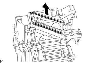
Remove the No. 2 combination meter mirror as shown in the illustration.
-
-
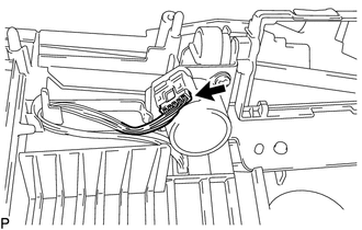
REMOVE COMBINATION METER WIRE
-
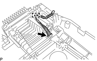
Disengage the clamp and disconnect the connector to remove the combination meter wire.
-
-
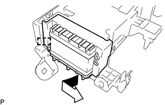
REMOVE METER CIRCUIT PLATE SUB-ASSEMBLY
-
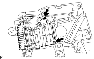
Remove the 2 screws.
-
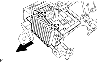
Pull the meter circuit plate sub-assembly in the direction indicated by the arrow to disengage the 2 guides and remove the meter circuit plate sub-assembly.
-