FRONT STABILIZER BAR INSTALLATION
PROCEDURE
INSTALL FRONT STABILIZER LOWER BRACKET BUSH LH
-
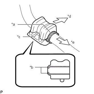
Install the front stabilizer lower bracket bush to the front stabilizer bar as shown in the illustration.
Table 1. Text in Illustration *a
Stopper
*b
Dust Lip
*c
Cutout
*d
Front of the Vehicle
*e
Inside of the Vehicle
Note:If replacing the front stabilizer bar, be sure to also replace the front stabilizer lower bracket bush.
Install the front stabilizer lower bracket bush so that the dust lips face the outside of the vehicle.
Install the front stabilizer lower bracket bush so that the cutout faces the rear of the vehicle.
-
INSTALL FRONT STABILIZER LOWER BRACKET BUSH RH
Tip:Perform the same procedure as for the LH side.
INSTALL FRONT STABILIZER BAR
Install the front stabilizer bar to the front suspension crossmember so that the identification mark is positioned on the right side of the vehicle.
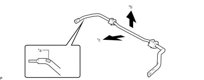
Table 2. Text in Illustration *a
Identification Mark
*b
Top of the Vehicle
*c
Front of the Vehicle
-
-
INSTALL FRONT SUSPENSION MEMBER FRONT BRACE LH
-
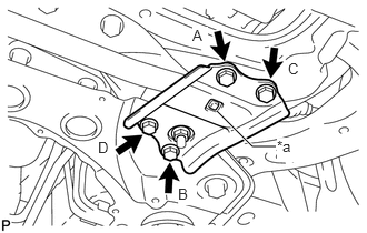
Install the front brace with the 4 bolts.
92 N*m
938 kgf*cm
68 ft.*lbf
Table 3. Text in Illustration *a
Protrusion
Note:Tighten the bolts in the order of B, C, D and A.
Make sure that the protrusion of the front stabilizer lower bracket bush protrudes from the hole of the front suspension member front brace LH when installing the front suspension member front brace LH.
-
INSTALL FRONT SUSPENSION MEMBER FRONT BRACE RH
-
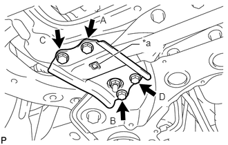
Install the front brace with the 4 bolts.
92 N*m
938 kgf*cm
68 ft.*lbf
Table 4. Text in Illustration *a
Protrusion
Note:Tighten the bolts in the order of B, C, D and A.
Make sure that the protrusion of the front stabilizer lower bracket bush protrudes from the hole of the front suspension member front brace RH when installing the front suspension member front brace RH.
-
TEMPORARILY INSTALL FRONT NO. 1 LOWER SUSPENSION ARM SUB-ASSEMBLY LH
INSTALL FRONT SUSPENSION CROSSMEMBER SUB-ASSEMBLY
INSTALL FRONT SUSPENSION MEMBER REAR BRACE LH
INSTALL FRONT SUSPENSION MEMBER REAR BRACE RH
INSTALL REAR SIDE RAIL REINFORCEMENT SUB-ASSEMBLY LH
INSTALL REAR SIDE RAIL REINFORCEMENT SUB-ASSEMBLY RH
INSTALL FRONT LOWER ENGINE MOUNTING BRACKET REINFORCEMENT
CONNECT FRONT NO. 1 LOWER SUSPENSION ARM SUB-ASSEMBLY LH
CONNECT FRONT NO. 1 LOWER SUSPENSION ARM SUB-ASSEMBLY RH
Tip:Perform the same procedure as for the LH side.
CONNECT TIE ROD END SUB-ASSEMBLY LH
CONNECT TIE ROD END SUB-ASSEMBLY RH
Tip:Perform the same procedure as for the LH side.
CONNECT FRONT STABILIZER LINK ASSEMBLY LH
CONNECT FRONT STABILIZER LINK ASSEMBLY RH
Tip:Perform the same procedure as for the LH side.
INSTALL NO. 1 STEERING COLUMN HOLE COVER SUB-ASSEMBLY
CONNECT NO. 2 STEERING INTERMEDIATE SHAFT ASSEMBLY
INSTALL COLUMN HOLE COVER SILENCER SHEET
INSTALL NO. 2 ENGINE UNDER COVER
INSTALL REAR ENGINE UNDER COVER LH
INSTALL REAR ENGINE UNDER COVER RH
Tip:Perform the same procedure as for the LH side.
INSTALL FRONT WHEELS
103 N*m
1050 kgf*cm
76 ft.*lbf
STABILIZE SUSPENSION
TIGHTEN FRONT NO. 1 LOWER SUSPENSION ARM SUB-ASSEMBLY LH
INSTALL CENTER NO. 4 ENGINE UNDER COVER
INSTALL NO. 1 ENGINE UNDER COVER (for 1ZR-FAE, 2ZR-FAE)
INSTALL NO. 1 ENGINE UNDER COVER (for 1WW)
INSPECT AND ADJUST FRONT WHEEL ALIGNMENT
Inspect and adjust the front wheel alignment (Click here).