EMISSION CONTROL SYSTEM SYSTEM DIAGRAM
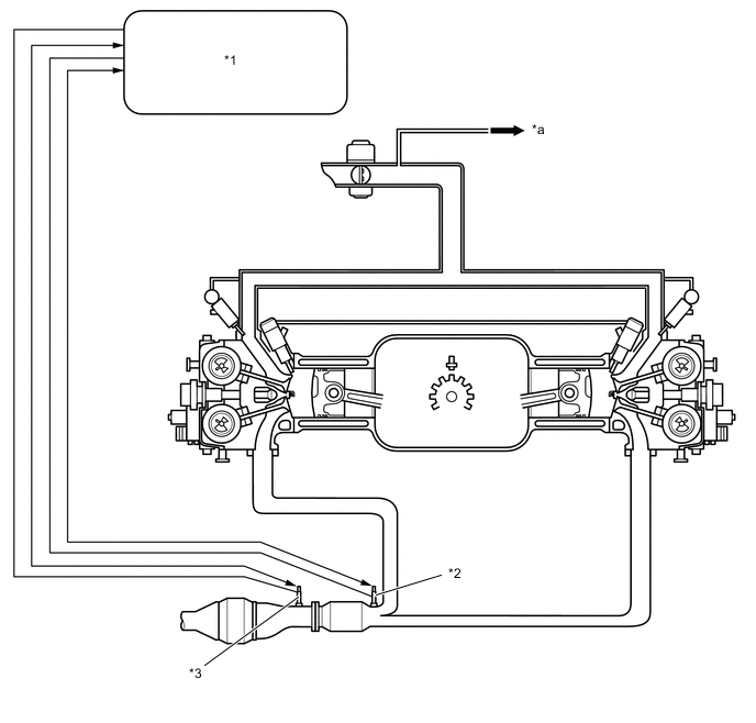
| *1 | ECM | *2 | Air Fuel Ratio Sensor |
| *3 | Heated Oxygen Sensor | - | - |
| *a | to Charcoal Canister Assembly | - | - |
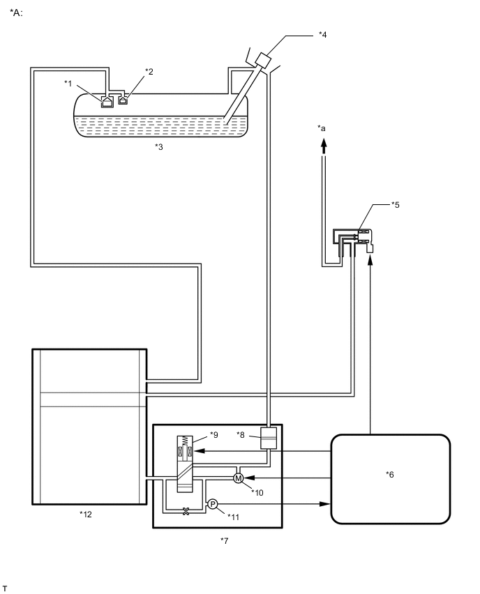
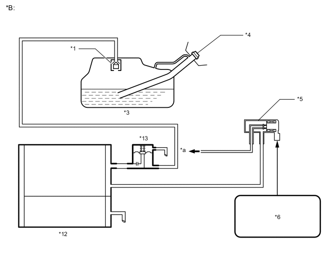
| *A | for Metal Type | *B | for Clamp Type |
| *1 | Roll Over Valve | *2 | Cut-off Valve |
| *3 | Fuel Tank Assembly | *4 | Fuel Tank Cap Assembly |
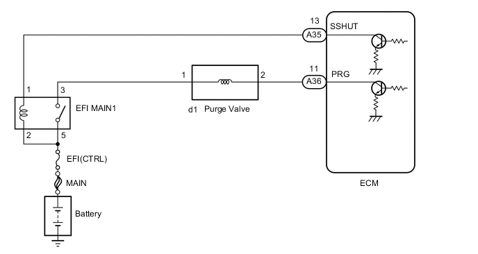
| *5 | Purge Valve | *6 | ECM |
| *7 | Canister Pump Module | *8 | Air Filter |
| *9 | Vent Valve | *10 | Pump Motor |
| *11 | Canister Pressure Sensor | *12 | Charcoal Canister Assembly |
| *13 | Fuel Outlet Valve Assembly | - | - |
| *a | to Intake Manifold | - | - |