WINDSHIELD GLASS REMOVAL
Tech Tips
A bolt without a torque specification is shown in the standard bolt chart Click here.
-
DISCONNECT CABLE FROM NEGATIVE BATTERY TERMINAL
CAUTION:
Wait at least 90 seconds after disconnecting the cable from the negative (-) battery terminal to prevent airbag and seat belt pretensioner activation.
-
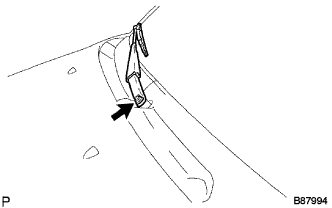
REMOVE FRONT WIPER ARM HEAD CAP
-
Remove the 2 caps.
-
-
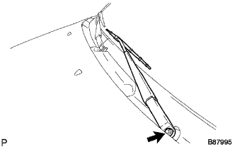
REMOVE FRONT WIPER ARM AND BLADE ASSEMBLY LH
-
Remove the nut and arm & blade.
-
-
REMOVE FRONT WIPER ARM AND BLADE ASSEMBLY RH
-
Remove the nut and arm & blade.
-
-
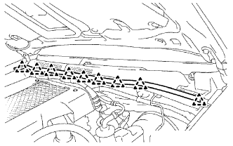
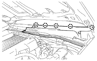
REMOVE HOOD TO COWL TOP SEAL
-
Detach the 9 clips and remove the seal.
-
-
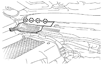
REMOVE COWL TOP VENTILATOR LOUVER LH
-
Detach the 4 claws and remove the louver.
-
-
REMOVE COWL TOP VENTILATOR LOUVER RH
-
Detach the 5 claws and remove the louver.
-
-
REMOVE FRONT DOOR OPENING TRIM LH
-
Partially remove the front door opening trim LH so that the front pillar garnish LH can be removed Click here.
-
-
REMOVE FRONT DOOR OPENING TRIM RH
-
Partially remove the front door opening trim RH so that the front pillar garnish RH can be removed Click here.
-
-
REMOVE FRONT NO. 1 ASSIST GRIP PLUG LH (w/ Assist Grip)
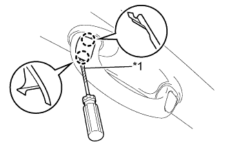
Text in Illustration *1 Tape Tech Tips
Use the same procedure for both assist grip plugs LH.
-
Using a screwdriver, detach the 2 claws and remove the assist grip plug LH.
Tech Tips
Tape the screwdriver tip before use.
-
-
REMOVE FRONT NO. 1 ASSIST GRIP PLUG RH (w/ Assist Grip)
Tech Tips
Use the same procedure described for the LH side.
-
REMOVE FRONT ASSIST GRIP SUB-ASSEMBLY (w/ Assist Grip)
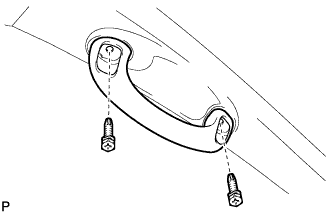
Tech Tips
Use the same procedure for both front assist grip sub-assemblies.
-
Remove the 2 screws and front assist grip sub-assembly.
-
-
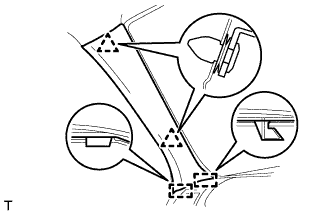
REMOVE FRONT PILLAR GARNISH LH
-
Detach the 2 clips and 2 guides and remove the front pillar garnish LH.
-
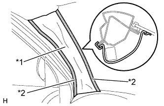
Text in Illustration *1 Protective Cover *2 Adhesive Tape w/ Curtain Shield Airbag:
Protect the curtain shield airbag assembly.
-
Thoroughly cover the airbag with a cloth or nylon sheet and fix the ends of the cover with adhesive tape as shown in the illustration.
Note
Cover the curtain shield airbag with a protective cover as soon as the front pillar garnish LH is removed.
-
-
-
REMOVE FRONT PILLAR GARNISH RH
Tech Tips
Use the same procedure described for the LH side.
-
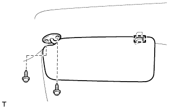
REMOVE VISOR ASSEMBLY LH
-
Detach the guide.
-
Remove the 2 screws and visor assembly LH.
-
-
REMOVE VISOR ASSEMBLY RH
Tech Tips
Use the same procedure described for the LH side.
-
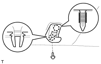
REMOVE VISOR HOLDER LH
-
Remove the screw.
-
Detach the 2 claws and remove the visor holder LH.
-
-
REMOVE VISOR HOLDER RH
Tech Tips
Use the same procedure described for the LH side.
-
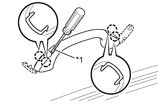
REMOVE ASSIST GRIP (w/ Assist Grip)
Tech Tips
Use the same procedure for all assist grips.
-
Using a screwdriver, detach the 4 claws and open the 2 covers.
Tech Tips
Tape the screwdriver tip before use.
Text in Illustration *1 Tape -
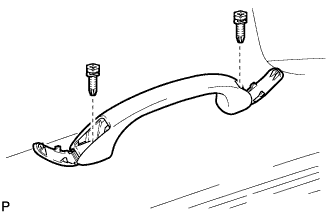
Remove the 2 screws and assist grip.
-
-
REMOVE NO. 1 ROOM LIGHT ASSEMBLY
-
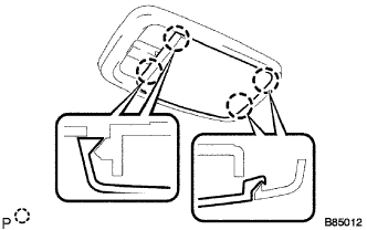
Using a screwdriver, detach the 4 claws and remove the lens.
Tech Tips
Tape the screwdriver tip before use.
-
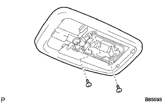
Remove the 2 screws and room light.
-
Disconnect the lamp connector.
-
-
REMOVE INNER REAR VIEW MIRROR ASSEMBLY
-
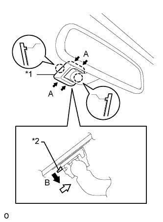
Text in Illustration *1 Cover *2 Claw w/o Screw:
-
Push the cover in the direction indicated by the arrows labeled A and remove it.
-
While holding down the claw in the direction of the black arrow labeled B, slide the inner rear view mirror assembly in the direction of the white arrow and remove it.
-
-
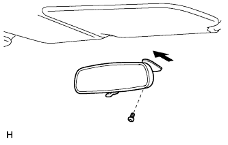
w/ Screw:
-
Using a T20 "TORX" socket wrench, remove the screw.
-
Slide the inner rear view mirror assembly in the direction of the arrow and remove it.
-
-
-
REMOVE ROOF HEADLINING ASSEMBLY
Tech Tips
It is not necessary to completely remove the roof headlining. Slightly lower the front section of the roof headlining.
For single cab Click here
For extra cab Click here
For double cab Click here
-
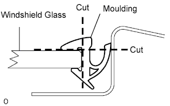
REMOVE WINDSHIELD MOULDING OUTER UPPER
-
Using a knife, cut off the moulding as shown in the illustration.
Note
Be careful not to damage the vehicle body.
-
Remove the remaining moulding.
Tech Tips
Make a partial cut in the moulding. Then pull and remove it by hand.
-
-
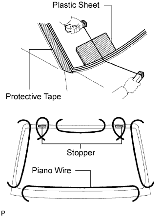
REMOVE WINDSHIELD GLASS
-
Apply protective tape to the outer surface of the vehicle body to prevent scratches.
-
From the interior, insert a piano wire between the vehicle body and glass as shown in the illustration.
-
Tie objects that can serve as handles (for example, wooden blocks) to all wire ends.
Note
-
When separating the glass from the vehicle, be careful not to damage the vehicle's paint or interior/exterior ornaments.
-
To prevent the instrument panel from being scratched when removing the glass, place a plastic sheet between the piano wire and instrument panel.
-
-
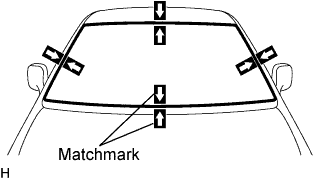
Place matchmarks over the glass and vehicle body on the locations indicated in the illustration.
Tech Tips
Matchmarks do not need to be place if not reusing the glass.
-
Cut through the adhesive by pulling the piano wire around the glass.
Note
Leave as much adhesive on the vehicle body as possible when cutting through the adhesive.
-
Disengage the stoppers.
-
Using suction cups, remove the glass.
-
-
CLEAN WINDSHIELD GLASS
-
Using a scraper, remove the damaged stoppers, dams and adhesive sticking to the glass.
-
Clean the outer edges of the glass with non-residue solvent.
Note
Do not touch the glass surface after cleaning it.Even if using new glass, clean it with non-residue solvent.
-
-
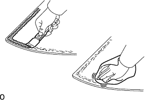
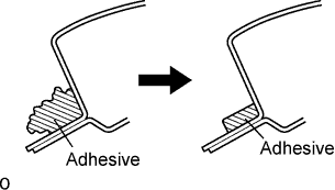
CLEAN VEHICLE BODY
-
Clean and shape the contact surface of the vehicle body.
-
On the contact surface of the vehicle body, use a knife to cut away excess adhesive as shown in the illustration.
Tech Tips
Leave as much adhesive on the vehicle body as possible.
Note
Be careful not to damage the vehicle body.
-
-
Clean the contact surface of the vehicle body with cleaner.
Tech Tips
Even if all the adhesive has been removed, clean the vehicle body.
-