AUDIO AND VISUAL SYSTEM(except 8 Speakers), Diagnostic DTC:B1567
| DTC Code | DTC Name |
|---|---|
| B1567 | HUD Disconnected |
DESCRIPTION
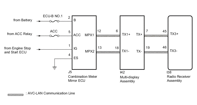
The multi-display and combination meter mirror ECU or multi-display and radio receiver assembly are connected by the AVC-LAN communication line. When an AVC-LAN communication error occurs between the combination meter mirror ECU and the radio receiver assembly, this DTC will be stored.
| DTC No. | Detection Item | DTC Detection Condition | Trouble Area |
|---|---|---|---|
| B1567 | HUD Disconnected | A device that is listed in the AVC-LAN connected device record of the master unit is missing. |
|
Tech Tips
For the AVC-LAN communication line, the radio receiver assembly is the master unit.
WIRING DIAGRAM
-
w/ Stop and Start System
-
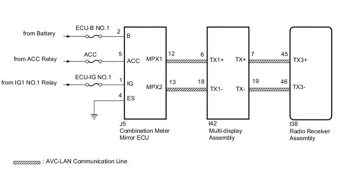
w/o Stop and Start System
CAUTION / NOTICE / HINT
Note
-
Inspect the fuses for circuits related to this system before performing the following inspection procedure.
-
Depending on the parts that are replaced during vehicle inspection or maintenance, performing initialization, registration or calibration may be needed. Refer to precaution for audio and visual system.
PROCEDURE
-
CHECK DTC
-
Clear the DTCs.
Body Electrical > Navigation System > Clear DTCs -
Recheck for DTCs and check that no DTCs are output.
Body Electrical > Navigation System > Trouble CodesOK No DTCs are output. Result Proceed to OK NG
OK 
USE SIMULATION METHOD TO CHECK Click here
NG 
-
-
CHECK HARNESS AND CONNECTOR (COMBINATION METER MIRROR ECU - BATTERY AND BODY GROUND)
-
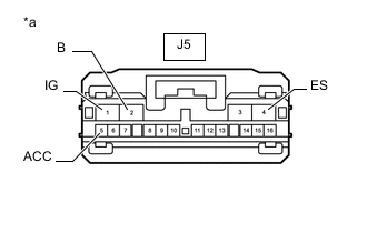
*a Front view of wire harness connector
(to Combination Meter Mirror ECU)
Disconnect the combination meter mirror ECU connector.
-
Measure the resistance according to the value(s) in the table below.
Standard Resistance Tester Connection Condition Specified Condition J5-4 (ES) - Body ground Always Below 1 Ω -
Measure the voltage according to the value(s) in the table below.
Standard Voltage w/ Stop and Start System Tester Connection Condition Specified Condition J5-1 (IG) - Body ground Engine switch on (IG) 10.5 to 16 V J5-2 (B) - Body ground Always 11 to 14 V J5-5 (ACC) - Body ground Engine switch on (ACC) 11 to 14 V w/o Stop and Start System Tester Connection Condition Specified Condition J5-1 (IG) - Body ground Engine switch on (IG) 11 to 14 V J5-2 (B) - Body ground Always 11 to 14 V J5-5 (ACC) - Body ground Engine switch on (ACC) 11 to 14 V Result Proceed to OK NG
NG
REPAIR OR REPLACE HARNESS OR CONNECTOR
OK
-
-
INSPECT RADIO RECEIVER ASSEMBLY
-
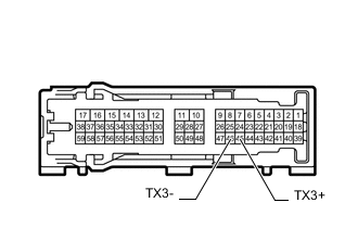
Remove the radio receiver assembly.
-
Measure the resistance according to the value(s) in the table below.
Standard Resistance Tester Connection Condition Specified Condition 45 (TX3+) - 46 (TX3-) Always 60 to 80 Ω Result Proceed to OK NG
NG
REPLACE RADIO RECEIVER ASSEMBLY Click here
OK
-
-
CHECK HARNESS AND CONNECTOR (COMBINATION METER MIRROR ECU - MULTI-DISPLAY ASSEMBLY)
-
Disconnect the J5 combination meter mirror ECU connector.
-
Disconnect the I42 multi-display assembly connector.
-
Measure the resistance according to the value(s) in the table below.
Standard Resistance Tester Connection Condition Specified Condition J5-12 (MPX1) - I42-6 (TX1+) Always Below 1 Ω J5-13 (MPX2) - I42-18 (TX1-) Always Below 1 Ω J5-12 (MPX1) or I42-6 (TX1+) - Body ground Always 10 kΩ or higher J5-13 (MPX2) or I42-18 (TX1-) - Body ground Always 10 kΩ or higher Result Proceed to OK NG
NG
REPAIR OR REPLACE HARNESS OR CONNECTOR
OK
-
-
CHECK COMBINATION METER MIRROR ECU
-
Replace the combination meter mirror ECU.
-
Clear the DTCs.
Body Electrical > Navigation System > Clear DTCs -
Recheck for DTCs and check that no DTCs are output.
Body Electrical > Navigation System > Trouble CodesOK No DTCs are output. Result Proceed to OK NG
OK
END (COMBINATION METER MIRROR ECU IS DEFECTIVE)
NG
-
-
CHECK MULTI-DISPLAY ASSEMBLY
-
Replace the multi-display assembly.
-
Clear the DTCs.
Body Electrical > Navigation System > Clear DTCs -
Recheck for DTCs and check that no DTCs are output.
Body Electrical > Navigation System > Trouble CodesOK No DTCs are output. Result Proceed to OK NG
OK
END (MULTI-DISPLAY ASSEMBLY IS DEFECTIVE)
NG
REPLACE RADIO RECEIVER ASSEMBLY Click here
-