REAR DOOR REASSEMBLY

CAUTION / NOTICE / HINT
Tech Tips
-
Use the same procedure for RHD and LHD vehicles.
-
The procedure listed below is for LHD vehicles.
-
Use the same procedure for the RH and LH sides.
-
The procedure listed below is for the LH side.
-
A bolt without a torque specification is shown in the standard bolt chart.
PROCEDURE
-
REPAIR INSTRUCTION
-
INSTALL NO. 3 BLACK OUT TAPE LH
-
INSTALL NO. 2 BLACK OUT TAPE LH
-
INSTALL NO. 1 BLACK OUT TAPE LH
-
INSTALL REAR DOOR REAR WINDOW FRAME MOULDING LH
-
INSTALL REAR DOOR UPPER WINDOW FRAME MOULDING LH
-
INSTALL REAR DOOR FRONT WINDOW FRAME MOULDING LH
-
INSTALL REAR DOOR NO. 3 WEATHERSTRIP LH
Tech Tips
When installing the rear door No. 3 weatherstrip LH, heat the rear door panel using a heat light.
Standard Item Temperature Rear Door Panel 40 to 60°C (104 to 140°F) Note
Do not heat the rear door panel and rear door No. 3 weatherstrip LH excessively.
-
Clean the rear door panel surface.
-
Using a heat light, heat the rear door panel surface.
-
Remove the double-sided tape from the rear door panel surface.
-
Wipe off any tape adhesive residue with cleaner.
-
-
Install a new rear door No. 3 weatherstrip LH.
-
Using a heat light, heat the rear door panel surface.
-
Remove the peeling paper from the face of the rear door No. 3 weatherstrip LH.
Tech Tips
After removing the peeling paper, keep the exposed adhesive free from foreign matter.
-
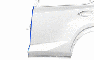
Install the rear door No. 3 weatherstrip LH as shown in the illustration.
Tech Tips
Press the rear door No. 3 weatherstrip LH firmly to install it.
-
-
-
INSTALL REAR DOOR BELT MOULDING ASSEMBLY LH
-
INSTALL OUTSIDE MOULDING RETAINER
-
INSTALL NO. 2 MOULDING TAPE
-
INSTALL REAR DOOR REAR OUTSIDE MOULDING PAD
-
INSTALL REAR DOOR NO. 1 MOULDING PAD
-
INSTALL REAR DOOR REAR UPPER OUTSIDE MOULDING LH
-
INSTALL REAR DOOR NO. 2 WEATHERSTRIP LH
-
INSTALL REAR DOOR UPPER OUTSIDE MOULDING PAD
-
INSTALL REAR DOOR LOWER OUTSIDE MOULDING SUB-ASSEMBLY LH
-
INSTALL REAR DOOR PANEL CUSHION
-
Install the rear door panel cushion.
-
-
INSTALL REAR DOOR FRAME GARNISH LH
-
Install a new rear door frame garnish LH.
-
-
INSTALL REAR DOOR WEATHERSTRIP LH
-
Attach the 25 clips to install the rear door weatherstrip LH.
-
-
INSTALL REAR DOOR CHECK ASSEMBLY LH
-
Apply MP grease to the sliding area of the rear door check assembly LH.
-
When reusing a bolt:
-
Clean the threads of the bolt with non-residue solvent.
-
Apply adhesive to the threads of the bolt.
Adhesive Toyota Genuine Adhesive 1324, Three Bond 1324 or equivalent.
-
-
Install the rear door check assembly LH to the door panel with the 2 nuts.
- Torque:
- 8.0 N*m { 82 kgf*cm, 71 in.*lbf }
-
Install the rear door check assembly LH to the body panel with the bolt.
- Torque:
- 27 N*m { 275 kgf*cm, 20 ft.*lbf }
-
-
INSTALL DOOR OUTSIDE HANDLE BUSH
-
Install the door outside handle bush.
-
-
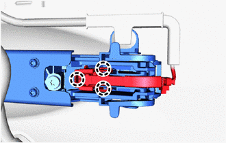
INSTALL REAR DOOR OUTSIDE HANDLE FRAME SUB-ASSEMBLY LH
-
Apply MP grease to the sliding area of the rear door outside handle frame sub-assembly LH.
-
Temporarily install the rear door outside handle frame sub-assembly LH as shown in the illustration.
-
Using a T30 "TORX" socket wrench, attach the clamp to install the rear door outside handle frame sub-assembly LH with the screw.
- Torque:
- 4.0 N*m { 41 kgf*cm, 35 in.*lbf }
-
-
INSTALL REAR DOOR FRONT OUTSIDE HANDLE PAD
-
Attach the 3 claws to install the rear door front outside handle pad.
-
-
INSTALL REAR DOOR REAR OUTSIDE HANDLE PAD
-
Attach the 4 claws to install the rear door rear outside handle pad.
-
-
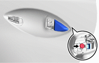
INSTALL REAR DOOR OUTSIDE HANDLE COVER LH
-
Using a T30 "TORX" socket wrench, install the rear door outside handle cover LH with the screw.
-
-
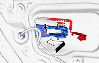
INSTALL REAR DOOR OUTSIDE HANDLE ASSEMBLY LH
-
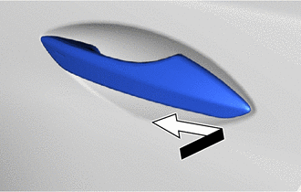
Temporarily install the rear door outside handle assembly LH in the direction of the arrow shown in the illustration.
-
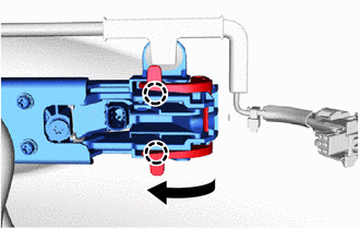
Attach the 2 claws to install the holder to the rear door outside handle assembly LH.
-
Attach the 3 claws to connect the connector and connector cover.
-
-
INSTALL REAR DOOR LOCK ASSEMBLY LH
-
INSTALL REAR DOOR LOCK CHILD PROTECTION COVER
-
Install the rear door lock child protection cover.
-
-
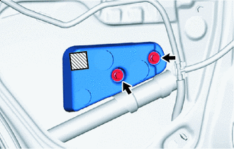
INSTALL REAR DOOR STIFFENER CUSHION LH (w/ Stiffener Cushion)
-

Double-sided Tape Clean vehicle installation surface.
-
Remove any remaining double-sided tape from the vehicle installation surface.
-
Clean the rear door panel sub-assembly installation surface with non-residue solvent.
-
-
Remove the peeling paper on a new rear door stiffener cushion LH while making sure not to touch the adhesional surface.
-
Install the rear door stiffener cushion LH with the 2 bolts.
- Torque:
- 6.2 N*m { 63 kgf*cm, 55 in.*lbf }
-
Press the rear door stiffener cushion LH against the door panel.
-
-
INSTALL REAR DOOR WINDOW REGULATOR SUB-ASSEMBLY LH
-
Apply MP grease to the sliding and rotating areas of the rear door window regulator sub-assembly LH.
-
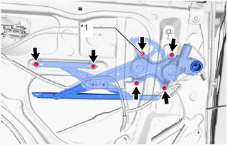
*1 Temporarily Bolt Temporarily install the temporarily bolt to the rear door window regulator sub-assembly LH.
-
Install the rear door window regulator sub-assembly LH with the 5 bolts, and then tighten the temporarily bolt.
- Torque:
- 8.0 N*m { 82 kgf*cm, 71 in.*lbf }
Tech Tips
Tighten the bolts in the order shown in the illustration.
Note
Be careful not to drop the rear door window regulator as it may become damaged.
-
-
INSTALL REAR DOOR GLASS SUB-ASSEMBLY LH
-
Temporarily install the power window regulator switch assembly with rear door armrest base panel.
-
Connect the cable to the negative (-) battery terminal.
-
Move the rear door window regulator so that the rear door glass bolts can be seen.
-
Disconnect the cable from the negative (-) battery terminal.
Note
When disconnecting the cable, some systems need to be initialized after the cable is reconnected.
-
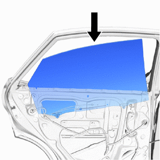
Insert the rear door glass sub-assembly LH as shown in the illustration.
Note
Do not damage the rear door glass sub-assembly.
-
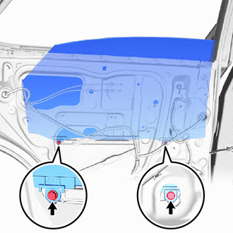
Install the rear door glass sub-assembly LH to the rear door window regulator sub-assembly LH with the 2 bolts.
- Torque:
- 8.0 N*m { 82 kgf*cm, 71 in.*lbf }
-
Install the hole plug.
-
-
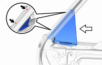
INSTALL REAR DOOR REAR GUIDE SEAL LH
-

Screw 
Attaching Direction Attach the rear door rear guide seal LH in the direction indicated by the arrow in the illustration.
-
Lift up the weatherstrip and install the rear door rear guide seal LH with the 2 screws.
-
-
INSTALL REAR DOOR REAR LOWER WINDOW FRAME SUB-ASSEMBLY LH
-
Bolt Screw Install the rear door rear lower window frame sub-assembly LH with the 2 screws.
-
Install the 2 bolts.
- Torque:
- 6.2 N*m { 63 kgf*cm, 55 in.*lbf }
-
-
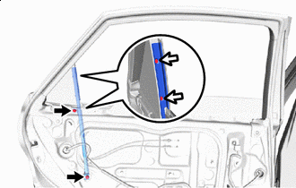
INSTALL REAR DOOR GLASS RUN LH
-
Install the rear door glass run LH.
-
-
INSTALL REAR DOOR SERVICE HOLE COVER LH
-
Apply new butyl tape to the rear door panel.
-
Pass each cable and connector through a new rear door service hole cover LH.
-
Align the rear door service hole cover LH to the specified positions on the rear door panel sub-assembly and attach it.
Tech Tips
Securely install the front door service hole cover LH by attaching it without any wrinkles or air bubbles.
-
Attach the clamp.
-
w/ Rear Speaker:
-
Attach the clamp.
-
-
Connect the 2 connectors.
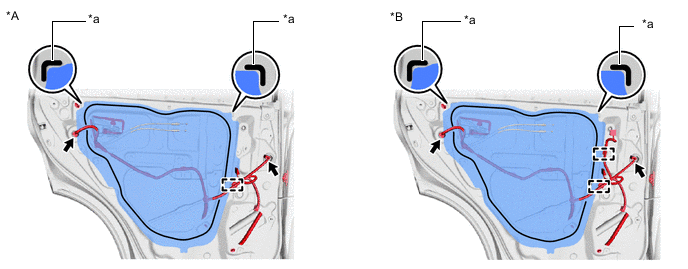
*A w/o Rear Speaker *B w/ Rear Speaker *a Reference Point - -
-
-
INSTALL REAR DOOR NO. 2 SERVICE HOLE COVER (w/o Rear Speaker)
-
Install the rear door No. 2 service hole cover with the 3 bolts.
-
-
INSTALL REAR SPEAKER ASSEMBLY (w/ Rear Speaker)
-
INSTALL REAR NO. 2 SPEAKER ASSEMBLY (w/ Rear Speaker)
-
INSTALL REAR DOOR ARMREST SET BRACKET LH
-
Install the rear door armrest set bracket LH with the 2 screws.
-
-
INSTALL REAR DOOR INNER GLASS WEATHERSTRIP LH
-
Install the rear door inner glass weatherstrip LH.
-
-
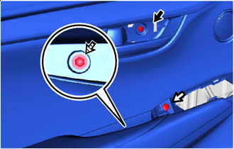
INSTALL REAR DOOR INSIDE HANDLE SUB-ASSEMBLY LH
-
Install the rear door inside handle sub-assembly LH with the 6 screws.
-
-
INSTALL REAR DOOR TRIM BOARD SUB-ASSEMBLY LH
-
Connect the rear door lock remote control cable assembly LH and rear door inside locking cable assembly LH.
-
Attach the 2 clamps.
-
Attach the 8 clips to install the rear door trim board sub-assembly LH.
-
w/ Rear Speaker:
-
Connect the connector.
-
-
Screw A Screw B 
Screw C Install the screw labeled A.
-
Install the screw labeled B.
-
Install the screw labeled C.
-
-
INSTALL REAR POWER WINDOW REGULATOR SWITCH ASSEMBLY WITH REAR DOOR ARMREST BASE PANEL
-
Connect the connector.
-
Attach the 4 claws, 2 clips to install the power window regulator switch assembly with rear door armrest base panel.
-
-
INSTALL REAR DOOR INSIDE HANDLE BEZEL PLUG LH
-
Attach the 3 claws to install the rear door inside handle bezel plug LH.
-
-
INSTALL REAR DOOR TRIM COVER LH
-
Install the rear door trim cover LH.
-
-
CONNECT CABLE TO NEGATIVE BATTERY TERMINAL
Note
When disconnecting the cable, some systems need to be initialized after the cable is reconnected.
-
CHECK SRS WARNING LIGHT
-
PERFORM DIAGNOSTIC SYSTEM CHECK
-
INITIALIZE POWER WINDOW CONTROL SYSTEM
-
CHECK POWER WINDOW CONTROL SYSTEM
-
CHECK POWER DOOR LOCK CONTROL SYSTEM