SLIDING ROOF SYSTEM, Diagnostic DTC:B2342
| DTC Code | DTC Name |
|---|---|
| B2342 | Switch Failure |
DESCRIPTION
This DTC is stored when the sliding roof drive gear sub-assembly (sliding roof ECU) detects that the sliding roof control switch is stuck for 30 seconds or more.
DTC No. |
Detection Item |
DTC Detection Condition |
Trouble Area |
|---|---|---|---|
B2342 |
Switch Failure |
Sliding roof drive gear sub-assembly (sliding roof ECU) detects sliding roof control switch is stuck for 30 seconds or more. |
|
WIRING DIAGRAM
Refer to DTC B2341.
CAUTION / NOTICE / HINT
When the sliding roof drive gear sub-assembly (sliding roof ECU) is removed and reinstalled or replaced, it requires initialization.
PROCEDURE
READ VALUE USING GTS
Connect the GTS to the DLC3.
Turn the power switch on (IG).
Turn the GTS on.
Enter the following menus: Body Electrical / Sliding Roof / Data List.
Read the Data List according to the display on the GTS.
Body Electrical > Sliding Roof > Data List
Tester Display
Measurement Item
Range
Normal Condition
Diagnostic Note
Open Switch Failure(Past)
Open switch failure signal (Past)
ON or OFF
ON: Sliding roof open switch failure signal (Past)
OFF: No sliding roof open switch failure signal (Past)
-
Close Switch Failure(Past)
Close switch failure signal (Past)
ON or OFF
ON: Sliding roof close switch failure signal (Past)
OFF: No sliding roof close switch failure signal (Past)
-
Up Switch Failure(Past)
Up switch failure signal (Past)
ON or OFF
ON: Sliding roof up switch failure signal (Past)
OFF: No sliding roof up switch failure signal (Past)
-
Down Switch Failure(Past)
Down switch failure signal (Past)
ON or OFF
ON: Sliding roof down switch failure signal (Past)
OFF: No sliding roof down switch failure signal (Past)
-
Open Switch Failure(Current)
Open switch failure signal (Current)
ON or OFF
ON: Sliding roof open switch failure signal (Current)
OFF: No sliding roof open switch failure signal (Current)
-
Close Switch Failure(Current)
Close switch failure signal (Current)
ON or OFF
ON: Sliding roof close switch failure signal (Current)
OFF: No sliding roof close switch failure signal (Current)
-
Up Switch Failure(Current)
Up switch failure signal (Current)
ON or OFF
ON: Sliding roof up switch failure signal (Current)
OFF: No sliding roof up switch failure signal (Current)
-
Down Switch Failure(Current)
Down switch failure signal (Current)
ON or OFF
ON: Sliding roof down switch failure signal (Current)
OFF: No sliding roof down switch failure signal (Current)
-
Body Electrical > Sliding Roof > Data List
Tester Display
Open Switch Failure(Past)
Close Switch Failure(Past)
Up Switch Failure(Past)
Down Switch Failure(Past)
Open Switch Failure(Current)
Close Switch Failure(Current)
Up Switch Failure(Current)
Down Switch Failure(Current)
Result
Proceed to
All items are displayed "OFF"
In part or in whole item displayed "ON"
All items are displayed "OFF" REPLACE SLIDING ROOF DRIVE GEAR SUB-ASSEMBLY (SLIDING ROOF ECU)
CHECK HARNESS AND CONNECTOR (SLIDING ROOF ECU - SLIDING ROOF CONTROL SWITCH AND BODY GROUND)
Disconnect the Q8 sliding roof drive gear sub-assembly (sliding roof ECU) connector.
Disconnect the Q16 map light assembly (sliding roof control switch) connector.
Measure the resistance according to the value(s) in the table below.
Standard Resistance
Tester Connection
Condition
Specified Condition
Q8-5 (CLS) - Q16-8 (CLS)
Always
Below 1 Ω
Q8-5 (CLS) - Body ground
Always
10 kΩ or higher
Q8-7 (OPN) - Q16-7 (OPN)
Always
Below 1 Ω
Q8-7 (OPN) - Body ground
Always
10 kΩ or higher
Q8-6 (DWN) - Q16-17 (DOWN)
Always
Below 1 Ω
Q8-6 (DWN) - Body ground
Always
10 kΩ or higher
Q8-4 (UP) - Q16-16 (UP)
Always
Below 1 Ω
Q8-4 (UP) - Body ground
Always
10 kΩ or higher
Q16-20 (GND) - Body ground
Always
Below 1 Ω
Q8-12 (E) - Body ground
Always
Below 1 Ω
Result
Proceed to
OK
NG
NG REPAIR OR REPLACE HARNESS OR CONNECTOR
INSPECT MAP LIGHT ASSEMBLY (SLIDING ROOF CONTROL SWITCH)
-
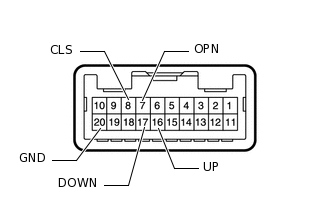
Remove the map light assembly (sliding roof control switch).
Measure the resistance according to the value(s) in the table below.
Standard Resistance
Tester Connection
Switch Condition
Specified Condition
16 (UP) - 20 (GND)
UP switch is pressed
Below 1 Ω
16 (UP) - 20 (GND)
UP switch is not pressed
10 kΩ or higher
17 (DOWN) - 20 (GND)
DOWN switch is pressed
Below 1 Ω
17 (DOWN) - 20 (GND)
DOWN switch is not pressed
10 kΩ or higher
7 (OPN) - 20 (GND)
OPEN switch is pressed
Below 1 Ω
7 (OPN) - 20 (GND)
OPEN switch is not pressed
10 kΩ or higher
8 (CLS) - 20 (GND)
CLOSE switch is pressed
Below 1 Ω
8 (CLS) - 20 (GND)
CLOSE switch is not pressed
10 kΩ or higher
Result
Proceed to
OK
NG
-