AIR CONDITIONING SYSTEM
-
SYSTEM CONTROL
-
Control List
-
The air conditioning system uses the following types of control.
Control Outline Air Conditioning Type Automatic Manual Outlet Air Temperature Control In compliance with the temperature set at the temperature control dial, the air conditioning control assembly (air conditioning ECU) calculates the outlet temperature based on the input signals from various sensors. In addition, corrections in accordance with the signals from the evaporator temperature sensor (No.1 cooler thermistor) and E.F.I. engine coolant temperature sensor are added to control the outlet air temperature. ○ - The temperature setting for the driver and front passenger is controlled independently in order to provide a separate vehicle interior temperature for the right and left side of the vehicle. Thus, air conditioning control that accommodates occupant preferences has been realized. ○ - Blower Control Controls the blower with fan motor sub-assembly in accordance with the airflow volume that has been calculated by the air conditioning control assembly (air conditioning ECU) based on the input signals from various sensors. ○ - Air Inlet Control Automatically controls the air inlet control damper in accordance with the outlet temperature that has been calculated by the air conditioning control assembly (air conditioning ECU). ○ - Drives the servo motor (for air inlet) according to the operation of the air inlet control switch and moves the dampers to the FRESH or RECIRC position. ○ ○
-
○: Equipped
-
-: Not equipped
-
-
-
-
CONSTRUCTION
-
Air Conditioning Control Panel
-
Various specialized dial-style air conditioning control panels have been adopted for vehicles equipped with auto air conditioners, vehicles equipped with manual air conditioners, and vehicles equipped without air conditioners.
-
A built-in air conditioning computer has been installed in the air conditioning control panel (air conditioning control assembly) for vehicles equipped with auto air conditioners.
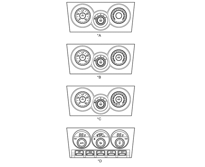
Text in Illustration *A Models without Air Conditioning System *B Models with Manual Air Conditioning System (Except Models for Korea) *C Models with Manual Air Conditioning System (Models for Korea) *D Models with Automatic Air Conditioning System
-
-
Air Conditioning Unit Assembly
-
The air conditioning unit assembly consists of the No.1 cooler evaporator sub-assembly, heater radiator unit sub-assembly, servo motors, evaporator temperature sensor (No.1 cooler thermistor) and blower with fan motor sub-assembly.
-
The No.1 cooler evaporator sub-assembly and heater radiator unit sub-assembly have been positioned horizontally in the unit, and the air conditioning unit assembly has been made smaller.

Text in Illustration *1 No.1 Cooler Evaporator Sub-assembly *2 Heater Radiator Unit Sub-assembly
-
-
No.1 Cooler Evaporator Sub-assembly
-
A Revolutionary super-slim Structure (RS) type evaporator is used. Placing the tanks at the top and the bottom of the evaporator and adopting a micropore tube construction has provided the following benefits:
-
Improved heat exchange efficiency
-
More uniform temperature distribution
-
A thinner evaporator

Text in Illustration *1 Tank *2 Cooling Fin *3 Micropore Tube - -
-
-
-
Evaporator Temperature Sensor (No.1 Cooler Thermistor)
-
The evaporator temperature sensor (No.1 cooler thermistor) detects the temperature of the cooled air immediately past the evaporator in the form of resistance changes, and outputs this data to the main body ECU (network gateway ECU)*1 or the air conditioning control assembly (air conditioning ECU)*2.
-
*1: Models with manual air conditioning system
-
*2: Models with automatic air conditioning system
-
-
-
Heater Radiator Unit Sub-assembly
-
The compact, lightweight and highly efficient Straight Flow Aluminum (SFA)-II type heater radiator unit sub-assembly is used for the air conditioning system.

Text in Illustration *1 Heater Radiator Unit Sub-assembly - -
-
-
Blower Motor Control (Models with Automatic Air Conditioning System)
-
The blower motor control has internal circuitry that uses electrical current to change the signal from the air conditioning control assembly (air conditioning ECU) and to change the speed of the blower with fan motor sub-assembly.

Text in Illustration *1 Blower Motor Control *2 Temperature Fuse *a To Air Conditioning Control Assembly (Air Conditioning ECU) *b To Blower with Fan Motor Sub-assembly
-
-
Blower Resistor (Models with Manual Air Conditioning System)
-
The blower resistor is a resistor that changes the speed of the blower with fan motor sub-assembly, and it has a temperature fuse installed in it.
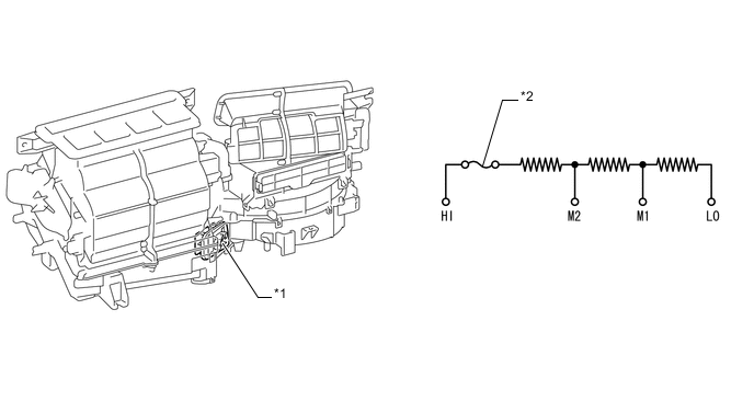
Text in Illustration *1 Blower Resistor *2 Temperature Fuse
-
-
Servo Motor (Models with Automatic Air Conditioning System)
-
A No.1 blower damper servo sub-assembly, No.1 air conditioning radiator damper servo sub-assembly, No.3 air conditioning radiator damper servo sub-assembly (driver), and No.3 air conditioning radiator damper servo sub-assembly (passenger) have been adopted.
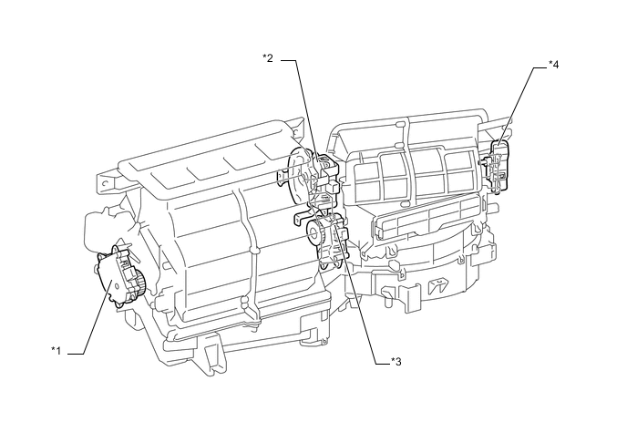
Text in Illustration *1 No.3 Air Conditioning Radiator Damper Servo Sub-assembly (Driver) *2 No.1 Air Conditioning Radiator Damper Servo Sub-assembly *3 No.3 Air Conditioning Radiator Damper Servo Sub-assembly (Passenger) *4 No.1 Blower Damper Servo Sub-assembly -
The No.1 blower damper servo sub-assembly receives an activation signal from the air conditioning control panel for its internal/fresh air select switch, whereupon it causes motor rotation and opens or closes the internal/fresh air door through a link.

Text in Illustration *1 Recirculated Air *2 Fresh Air *3 Internal air contact *4 Moving contact *5 Fresh air contact *6 Motor -
In the No.1 air conditioning radiator damper servo sub-assembly, the air conditioning control assembly (air conditioning ECU) causes the servo motor to rotate to a particular position due to action taken to change the mode of the air conditioning control assembly or by automatic control, causing the mode door to open or close through a link.
-
The actual position of the mode door is measured by a potentiometer installed in the No.1 air conditioning radiator damper servo sub-assembly, and the change in resistance caused by the change in door position is fed back into the air conditioning control assembly (air conditioning ECU) as a change in voltage.

Text in Illustration *1 DEF *2 F/D *3 FOOT *4 B/L *5 FACE *6 Potentiometer *7 Motor - - -
In the No.3 air conditioning radiator damper servo sub-assembly, the air conditioning control assembly (air conditioning ECU) causes the servo motor to rotate to a particular position due to action taken to set the temperature or by automatic control, causing the air mix door to open or close through a link.
-
The actual position of the air mix door is measured by a potentiometer installed in the No.3 air conditioning radiator damper servo sub-assembly (driver), and the change in resistance caused by the change in door position is fed back into the air conditioning control assembly (air conditioning ECU) as a change in voltage.

Text in Illustration *1 Max Cool *2 Max Hot *3 Potentiometer *4 Motor
-
-
Clean Air Filter
-
The adoption of a high-performance fine-dust clean air filter that uses electret* fibers provides pleasant air inside the vehicle through its ability to remove pollen, dust and other micron-sized particles as well as diesel carbon and other sub-micron particles that get inside the vehicle interior.
-
*: Electret: a material that produces a semi-permanent external electric field
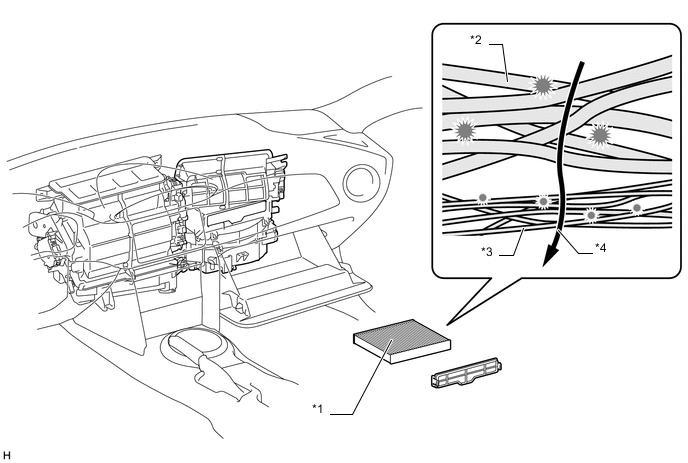
Text in Illustration *1 Clean Air Filter *2 Large Foreign Object Filter Layer *3 Electret Layer *4 Air Flow Tech Tips
The filter should be replaced regularly in order to maintain its dust collection capacity.
-
-
-
Cooler Condenser Assembly
-
A Multi-Flow (MF) type condenser is used. The cooler condenser assembly consists of 2 cooling portions: a condensing portion and a super-cooling portion. These portions are integrated with a gas-liquid separator (modulator). This cooler condenser assembly uses a sub-cool cycle that offers excellent heat-exchange performance.
-
In the sub-cool cycle, after the refrigerant passes through the condensing portion of the condenser, both the liquid refrigerant and the gaseous refrigerant that could not be liquefied are cooled again in the super-cooling portion. Thus, the refrigerant is sent to the evaporator in an almost completely liquefied state.
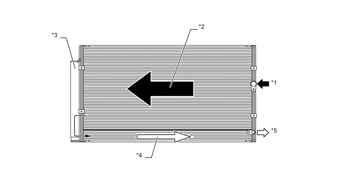
Text in Illustration *1 Gaseous Refrigerant *2 Condensing Portion *3 Modulator *4 Super-cooling Portion *5 Liquid Refrigerant - - Tech Tips
The point at which the air bubbles disappear in the refrigerant of the sub-cool cycle is lower than the proper amount of refrigerant with which the system must be filled. Therefore, if the system is recharged with refrigerant based on the point at which the air bubbles disappear, the amount of refrigerant would be insufficient. As a result, the cooling performance of the system would be affected. Overcharging the system with refrigerant will also lead to reduced performance. For the proper method of verifying the amount of refrigerant and for instructions on how to recharge the system with refrigerant. For details, refer to the Repair Manual.

*1 Proper Charge Amount *2 High Pressure *3 Point at which Bubbles Disappear *4 Amount of Refrigerant
-
-
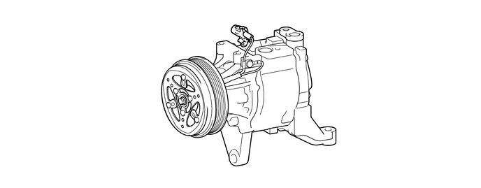
Compressor with Magnet Clutch
-
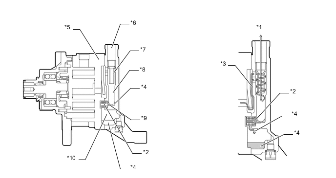
A compact and high performance scroll compressor with oil separator has been adopted.
-
The scroll compressor with oil separator consists of a spirally wound fixed scroll and rotating scroll that from a pair, and oil separator, and a magnetic clutch.
The fixed scroll is integrated with the housing. Because the rotation of the shaft causes the rotating scroll to revolve while maintaining the same posture, the volume of the space that is partitioned by both scrolls varies to perform the suction, compression, and the discharge of the refrigerant gas.
A pin is attached behind the rotating scroll to prevent the autorotation of the rotating scroll, allowing it only to revolve.
Locating the suction port directly above the scrolls enables direct suction, thus realizing improved suction efficiency.
Containing a built-in oil separator, this compressor is able to separate the compressor oil that is intermixed with the refrigerant and circulates in the refrigeration cycle, thus realizing a reduction in the oil circulation rate.

Text in Illustration *1 Fixed Scroll *2 Rotating Scroll *3 Pins *4 Shaft *5 Discharge Port - - -
A CS (Centrifugal with Shutter) type oil separator has been adopted to reduce the circulation rate of the compressor oil that is intermixed with the refrigerant and circulates in the refrigeration cycle.
This oil separator is provided with a cylindrical pipe in the separator case, enabling the refrigerant gas that has been discharged through the discharge gas inlet to be separated into refrigerant gas and oil through centrifugal force, and minimizing the outflow of the oil to the discharge service port. As a result, the oil circulation rate has been reduced and makes energy savings possible.
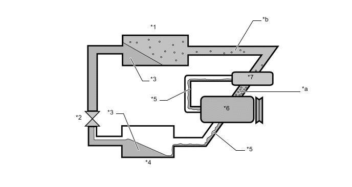
Text in Illustration *1 Cooler Condenser Assembly and Modulator *2 Cooler Expansion Valve *3 Refrigerant Gas + Compressor Oil *4 No.1 Cooler Evaporator Sub-assembly *5 Oil *6 Compressor with Magnet Clutch *7 Oil Separator - - *a Oil Circulation Ratio of 4% *b Oil Circulation Ratio of 1%
-
-
Cooler (Room Temp. sensor) Thermistor (Models with Automatic Air Conditioning System)
-
The cooler (room temp. sensor) thermistor detects the room temperature based on changes in the resistance of its built-in thermistor.
-
-
Thermistor Assembly (Models with Automatic Air Conditioning System)
-
The thermistor assembly detects the ambient temperature based on changes in the resistance of its built-in thermistor. This signal is used by the air conditioning control assembly (air conditioning ECU).
-
-
Automatic Light Control Sensor (Models with Automatic Air Conditioning System)
-
A single-unit light sensor has been adopted for the automatic light control sensor, reducing the part count.
-
Changes in the amount of light are detected by the scanner (integrated optical sensor) and output to the air conditioning control assembly (air conditioning ECU).
-
-
Air Conditioning Pressure Switch (Airconditioner Tube Assembly)
-
The air conditioning pressure switch (airconditioner tube assembly) uses refrigerant pressure to output an on/off signal to the ECM to control the compressor with magnet clutch.
-
-
-
OPERATION
-
Mode Position and Door Operation
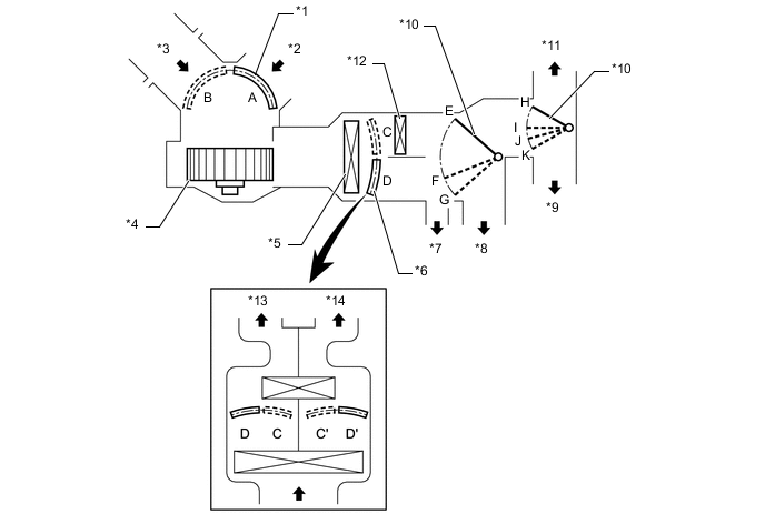
Text in Illustration *1 Air Inlet Control Door *2 Recirculated Air *3 Fresh Air *4 Blower with Fan Motor Sub-assembly *5 No.1 Cooler Evaporator Sub-assembly *6 Air Mix Control Door *7 Side Register *8 Center Register *9 Footwell Register Duct *10 Mode Control Door *11 Front Defroster, Side Defroster *12 Heater Radiator Unit Sub-assembly *13 Passenger Side *14 Driver Side Control Door Operation Position Door Position Operation Air Inlet Control Door FRESH A Brings in fresh air. (The internal air recirculates partially.) RECIRCULATION B Recirculates internal air. Air Mix Control Door MAX COLD to MAX HOT
Temperature Setting
C - D
(C' - D')
Varies the mixture ratio of warm air and cool air in order to regulate the temperature continuously between hot and cold. Mode Control Door 
FACE E, H Air blows out of the center register and side register ducts. 
BI-LEVEL F, H Air blows out of the center register, side register and footwell register ducts. 
FOOT G, I Air blows out of the footwell register and side register ducts. In addition, air blows out slightly from the front defroster and side defroster. 
FOOT AND DEFROSTER G, J Defrosts the windshield through the front defroster, side defroster and side register ducts, while air is also blown out from the footwell register ducts. 
DEFROSTER G, K Defrosts the windshield through the front defroster, side defroster and side register ducts. -
Air Outlets and Airflow Volume

Indication Mode Face Footwell Defroster Center Side Front Side A B C D E FACE 
- - - BI-LEVEL 
- - FOOT - 

FOOT AND DEFROSTER - DEFROSTER - - The size of the circle ○ indicates the proportion of airflow volume.
-
Compressor with Magnet Clutch Operation
-
As the capacity of the compression chamber, which is created between the rotating scroll and the fixed scroll, increases in accordance with the revolution of the rotating scroll, refrigerant gas is drawn in from the intake port.
-
From the state at which the suction process has been completed, as the revolution of the rotating scroll advances further, the capacity of the compression chamber decreases gradually. Consequently, the refrigerant gas that has been drawn in becomes compressed gradually and is sent to the center of the fixed scroll. The compression of the refrigerant gas is completed when the rotating scroll completes approximately 2 revolutions.
-
When the compression of the refrigerant gas is completed and the refrigerant pressure becomes high, the refrigerant gas discharges through the discharge port located in the center of the fixed scroll by pushing the discharge valve.
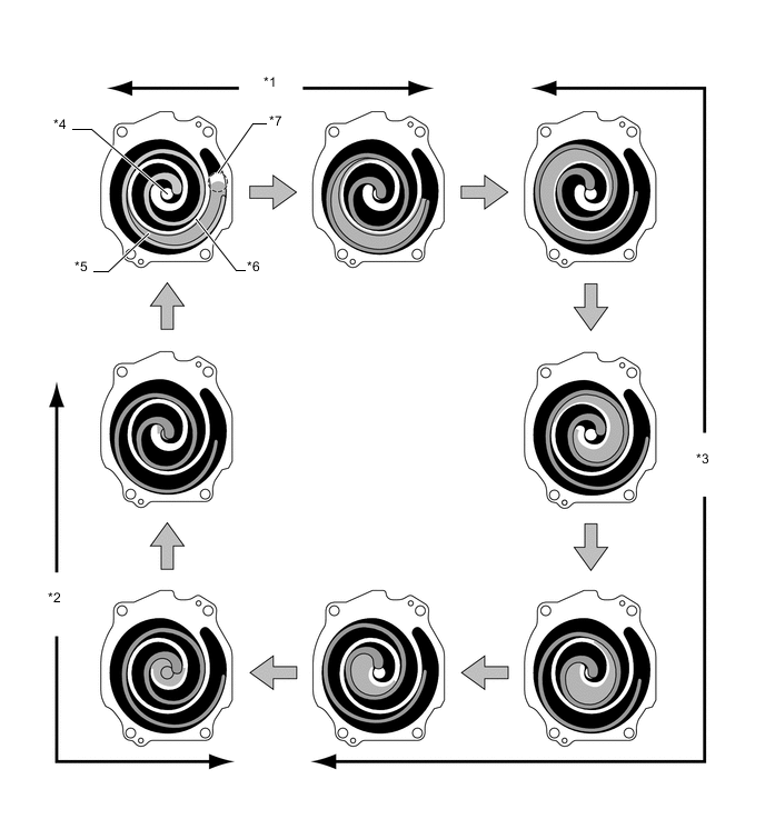
Text in Illustration *1 Suction *2 Discharge *3 Compression *4 Discharge Port *5 Rotating Scroll *6 Fixed Scroll *7 Intake Port - - -
The refrigerant gas that is discharged from the discharge port flows by rotating around the cylindrical pipe in the oil separator. At this time, the centrifugal force that is created during the rotation separates the refrigerant gas and the compressor oil due to the difference in their specific gravity. The refrigerant gas with the lighter specific gravity passes through the inside of the pipe and travels from the discharge service port to the outside of the compressor. The compressor oil with the heavier specific gravity is discharged through the oil discharge hole in the shutter and is stored in the oil storage chamber. Then, the compressor oil is fed again into the compressor and circulates inside the compressor.
Text in Illustration *1 Refrigerant *2 Shutter *3 Refrigerant and Compressor Oil *4 Compressor Oil *5 Valve Chamber D *6 Service Port *7 Pipe *8 Case *9 Oil Discharge Hole *10 Oil Storage Chamber
-
-
-
DIAGNOSIS
-
The air conditioning control assembly (air conditioning ECU) has a diagnosis function. It stores a record of air conditioning system failures in its memory in the form of Diagnostic Trouble Codes (DTCs).
-
There are 2 methods for reading DTCs. One is to use the Grobal TechStream (GTS), and the other is to read the DTCs using the air conditioning control assembly. For details, refer to the Repair Manual.
-