ROOF HEADLINING (for Double Cab) INSTALLATION
Tech Tips
-
Use the same procedure for RHD and LHD vehicles.
-
The procedure listed below is for LHD vehicles.
-
INSTALL REAR NO. 3 SIDE RAIL SPACER LH (w/o Curtain Shield Airbag)
-
Attach the 3 claws to install the rear No. 3 side rail spacer LH.
-
-
INSTALL REAR NO. 3 SIDE RAIL SPACER RH (w/o Curtain Shield Airbag)
Tech Tips
Use the same procedure described for the LH side.
-
INSTALL REAR NO. 2 SIDE RAIL SPACER LH (w/o Curtain Shield Airbag)
Tech Tips
Use the same procedure for both rear No. 2 side rail spacers LH.
-
Attach the 2 claws to install the rear No. 2 side rail spacer LH.
-
-
INSTALL REAR NO. 2 SIDE RAIL SPACER RH (w/o Curtain Shield Airbag)
Tech Tips
Use the same procedure described for the LH side.
-
INSTALL SIDE RAIL SPACER (for LHD, w/o Curtain Shield Airbag)
-
Attach the 2 claws to install the side rail spacer.
-
-
INSTALL SIDE RAIL SPACER (for RHD, w/o Curtain Shield Airbag)
Tech Tips
Use the same procedure described for LHD vehicles.
-
INSTALL FRONT SIDE RAIL SPACER LH (w/o Curtain Shield Airbag)
-
Attach the 2 claws to install the front side rail spacer LH.
-
-
INSTALL FRONT SIDE RAIL SPACER RH (w/o Curtain Shield Airbag)
Tech Tips
Use the same procedure described for the LH side.
-
INSTALL ROOF HEADLINING ASSEMBLY
-
for LHD:
-
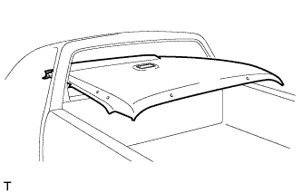
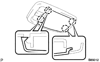
Place the roof headlining assembly into the vehicle as shown in the illustration.
Note
Be careful not to damage the roof headlining assembly when placing it.
-
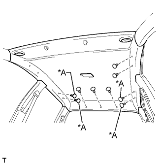
Text in Illustration *A w/o Assist Grip Install the roof headlining assembly with the clips.
-
Connect the connectors and attach the 4 clamps.
-
-
for RHD:
-
Place the roof headlining assembly into the vehicle as shown in the illustration.
Note
Be careful not to damage the roof headlining assembly when placing it.
-
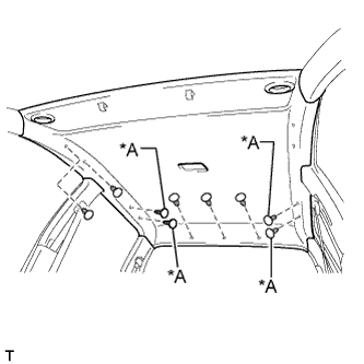
Install the roof headlining assembly with the clips.
-
Connect the connectors and attach the 5 clamps.
Text in Illustration *A w/o Assist Grip
-
-
Attach the 5 clamps to the front pillar.
-
-
INSTALL BACK WINDOW GLASS
-
INSTALL DEFROSTER NOZZLE ASSEMBLY (w/ Defroster)
-
Attach the 4 clips to install the defroster nozzle assembly.
-
-
INSTALL NO. 3 HEATER TO REGISTER DUCT
-
Attach the 4 claws to install the No. 3 heater to register duct.
-
Install the clip.
-
-
INSTALL NO. 1 HEATER TO REGISTER DUCT
-
Attach the 3 claws to install the No. 1 heater to register duct.
-
Install the clip.
-
-
INSTALL NO. 2 HEATER TO REGISTER DUCT
-
Install the No. 2 heater to register duct with the 3 clips.
-
-
INSTALL LOWER INSTRUMENT PANEL FINISH PANEL SUB-ASSEMBLY
-
Attach the 3 guides, 2 claws and 3 clips to install the lower instrument panel finish panel.
-
-
INSTALL UPPER INSTRUMENT PANEL SUB-ASSEMBLY
-
INSTALL ASSIST GRIP (w/ Assist Grip)
Tech Tips
Use the same procedure for all assist grips.
-
Install the assist grip with the 2 screws.
-
Install the screw.
-
-
INSTALL VISOR HOLDER LH
-
Attach the 2 claws to install the visor holder LH.
-
Install the screw.
-
-
INSTALL VISOR HOLDER RH
Tech Tips
Use the same procedure described for the LH side.
-
INSTALL VISOR ASSEMBLY LH
-
Install the visor assembly LH with the 2 screws.
-
Attach the guide.
-
-
INSTALL VISOR ASSEMBLY RH
Tech Tips
Use the same procedure described for the LH side.
-
INSTALL NO. 1 ROOM LIGHT ASSEMBLY
-
Connect the light connector.
-
Install the room light with the 2 screws.
-
Attach the lens with the 4 claws.
-
-
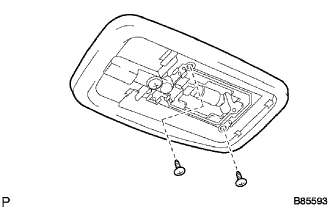
INSTALL MAP LIGHT ASSEMBLY
-
Connect the connector.
-
Attach the 2 guides and claw.
-
Install the 2 screws to install the map light assembly.
-
-
INSTALL QUARTER INSIDE TRIM BOARD LH
-
w/o Rear Center Seat Belt:
-
Attach the 4 clips to install the quarter inside trim board LH.
-
-
w/ Rear Center Seat Belt:
-
Attach the 4 clips to install the quarter inside trim board LH.
-
-
Connect the rear seat belt shoulder anchor with the bolt.
- Torque:
- 42 N*m { 428 kgf*cm, 31 ft.*lbf }
-
Attach the 2 claws to close the rear seat belt shoulder anchor cover.
-
-
INSTALL QUARTER INSIDE TRIM BOARD RH
Tech Tips
Use the same procedure described for the LH side.
-
INSTALL LOWER QUARTER TRIM PANEL LH
-
w/o Rear Center Seat Belt:
-
Attach the 3 clips and claw to install the lower quarter trim panel LH.
-
-
w/ Rear Center Seat Belt:
-
Attach the 3 clips and claw to install the lower quarter trim panel LH.
-
-
-
INSTALL LOWER QUARTER TRIM PANEL RH
Tech Tips
Use the same procedure described for the LH side.
-
INSTALL UPPER BACK PANEL GARNISH (w/o Rear Center Seat Belt)
-
Attach the 5 clips and 4 claws to install the upper back panel garnish.
-
-
INSTALL BACK PANEL TRIM (w/ Rear Center Seat Belt)
-
Attach the 2 claws and 9 clips to install the back panel trim.
-
Install the 4 clips.
-
Attach the 5 claws to connect the seat belt guide.
-
-
INSTALL CENTER PILLAR GARNISH LH
-
Attach the guide and clip to install the center pillar garnish LH.
-
Connect the front seat belt shoulder anchor with the bolt.
- Torque:
- 42 N*m { 428 kgf*cm, 31 ft.*lbf }
-
Attach the 4 claws to install the front seat belt shoulder anchor cover.
-
-
INSTALL CENTER PILLAR GARNISH RH
Tech Tips
Use the same procedure described for the LH side.
-
INSTALL LOWER CENTER PILLAR GARNISH LH
-
Attach the 2 clips and 2 claws to install the lower center pillar garnish LH.
-
Connect the front seat outer belt floor anchor with the bolt.
- Torque:
- 42 N*m { 428 kgf*cm, 31 ft.*lbf }
-
-
INSTALL LOWER CENTER PILLAR GARNISH RH
Tech Tips
Use the same procedure described for the LH side.
-
INSTALL REAR DOOR OPENING TRIM LH
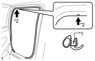
Text in Illustration *1 Paint Mark *2 Mark Position
-
Align the paint mark on the rear door opening trim LH with the mark position on the vehicle and install the rear door opening trim LH as shown in the illustration.
-
-
INSTALL REAR DOOR OPENING TRIM RH
Tech Tips
Use the same procedure described for the LH side.
-
INSTALL REAR DOOR SCUFF PLATE LH
-
Attach the 2 clips and 7 claws to install the rear door scuff plate LH.
-
-
INSTALL REAR DOOR SCUFF PLATE RH
Tech Tips
Use the same procedure described for the LH side.
-
INSTALL FRONT PILLAR GARNISH LH
-
w/ Curtain Shield Airbag:
-
Remove the protective cover.
-
-
Attach the 2 guides and 2 clips to install the front pillar garnish LH.
-
-
INSTALL FRONT PILLAR GARNISH RH
Tech Tips
Use the same procedure described for the LH side.
-
INSTALL FRONT ASSIST GRIP SUB-ASSEMBLY (w/ Assist Grip)
Tech Tips
Use the same procedure for both front assist grips sub-assemblies.
-
Install the front assist grip sub-assembly with the 2 screws.
-
-
INSTALL ASSIST GRIP PLUG LH (w/ Assist Grip)
Tech Tips
Use the same procedure for both assist grip plugs LH.
-
Attach the 2 claws to install the assist grip plug LH.
-
-
INSTALL ASSIST GRIP PLUG RH (w/ Assist Grip)
Tech Tips
Use the same procedure described for the LH side.
-
INSTALL FRONT DOOR OPENING TRIM LH
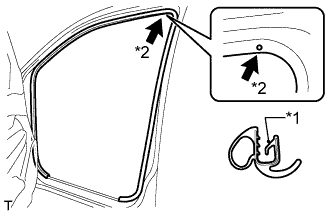
Text in Illustration *1 Paint Mark *2 Mark Position
-
Align the paint mark on the front door opening trim LH with the mark position on the vehicle and install the front door opening trim LH as shown in the illustration.
-
-
INSTALL FRONT DOOR OPENING TRIM RH
Tech Tips
Use the same procedure described for the LH side.
-
INSTALL FRONT DOOR SCUFF PLATE LH
-
Attach the 3 clips and 7 claws to install the front door scuff plate LH.
-
-
INSTALL FRONT DOOR SCUFF PLATE RH
Tech Tips
Use the same procedure described for the LH side.
-
INSTALL REAR SEAT ASSEMBLY
-
CONNECT CABLE TO NEGATIVE BATTERY TERMINAL (w/ Airbag System)
Note
When disconnecting the cable, some systems need to be initialized after the cable is reconnected Click here.
-
CHECK SRS WARNING LIGHT (w/ Airbag System)