ENTRY AND START SYSTEM(for Start Function), Diagnostic DTC:B2284
| DTC Code | DTC Name |
|---|---|
| B2284 | Brake Signal Malfunction |
DESCRIPTION
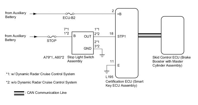
The certification ECU (smart key ECU assembly) receives brake signal information from 2 sources. It receives a signal from the stop light switch assembly via a direct line, and a signal from the skid control ECU via CAN communication. If the information from these 2 sources is inconsistent, this DTC will be stored.
Tech Tips
-
When the certification ECU (smart key ECU assembly) is replaced with a new one and the cable is connected to the negative (-) auxiliary battery terminal, the power source mode changes to on (IG).
-
When the auxiliary battery cable is disconnected and reconnected, the power source returns to the mode it was in before the auxiliary battery cable was disconnected.
| DTC No. | DTC Detection Condition | Trouble Area |
|---|---|---|
| B2284 | Stop light switch assembly operation information received by the certification ECU (smart key ECU assembly) from the stop light switch assembly via a direct line and stop light switch assembly information from the skid control ECU via CAN are inconsistent. |
|
This DTC is stored when a mismatch between the brake signal from the direct line and the brake signal sent via CAN communication is detected.
| DTC Code | DTC Detection Condition | Trouble Area | DTC Output Confirmation Operation |
|---|---|---|---|
| B2284 | The brake signal information from the direct line and the brake signal information from the ECU via CAN communication are inconsistent (1-trip detection logic*). |
|
Connect the cable to the negative (-) auxiliary battery terminal, turn the brakes off for 20 seconds or more and then turn them on for 20 seconds or more. |
-
*: Only output while a malfunction is present and the power switch is on (IG)
| Vehicle Condition when Malfunction Detected | Fail-safe Function when Malfunction Detected |
|---|---|
| When the key is inside the vehicle, the hybrid control system does not start even though a hybrid control system start operation is performed (the power switch indicator does not illuminate in green). However, if the power switch is pressed and held for a certain period of time after the power source mode is changed to on (ACC), the hybrid control system can be started.
|
- |
WIRING DIAGRAM
CAUTION / NOTICE / HINT
Tech Tips
Check the connector connection to the terminal to make sure that there is no abnormality such as a loose connection, deformation, etc.
Note
-
The entry and start system uses multiplex communication. First perform the inspections in "How to Proceed with Troubleshooting" to confirm that there are no communication malfunctions before proceeding with troubleshooting Click here.
-
Inspect the fuses for circuits related to this system before performing the following inspection procedure.
-
After performing repairs, perform the operation that fulfills the DTC output confirmation operation, and then confirm that no DTCs are output again.
Tech Tips
| DTC | Data List Item | Active Test Item |
|---|---|---|
| B2284 |
Power Source Control
ABS/VSC/TRAC |
- |
PROCEDURE
-
READ VALUE USING GTS (STOP LIGHT SWITCH1)
-
Connect the Techstream to the DLC3.
-
Turn the power switch on (IG).
-
Turn the Techstream on.
-
Enter the following menus: Body Electrical / Power Source Control / Data List.
-
Read the Data List according to the display on the Techstream.
Body Electrical > Power Source Control > Data List Tester Display Measurement Item Range Normal Condition Diagnostic Note Stop Light Switch1 Stop light switch1 ON or OFF ON: Brake pedal depressed
OFF: Brake pedal released
-
Use this item to determine whether the stop light switch is malfunctioning
-
The hybrid control system cannot be started when this item is OFF.
-
When this item is malfunctioning , the hybrid control system can be started by pressing and holding the power switch for a certain period of time.
-
OK 
GO TO HYBRID CONTROL SYSTEM (HOW TO PROCEED WITH TROUBLESHOOTING)
NG 
-
-
CHECK HARNESS AND CONNECTOR (POWER SOURCE)
-
Disconnect the L195 certification ECU (smart key ECU assembly) connector.
-
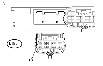
Text in Illustration *a Rear view of wire harness connector
(to Certification ECU (Smart Key ECU Assembly))
Measure the voltage according to the value(s) in the table below.
Standard Voltage Tester Connection Condition Specified Condition L195-2 (+B) - Body ground Power switch off 11 to 14 V
NG
REPAIR OR REPLACE HARNESS OR CONNECTOR IN CIRCUIT CONNECTED TO POWER SOURCE
OK
-
-
CHECK HARNESS AND CONNECTOR (GROUND)
-
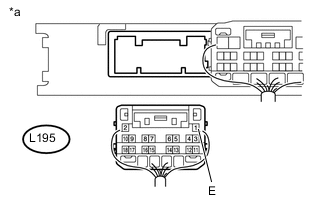
Text in Illustration *a Rear view of wire harness connector
(to Certification ECU (Smart Key ECU Assembly))
Measure the resistance according to the value(s) in the table below.
Standard Resistance Tester Connection Condition Specified Condition L195-11 (E) - Body ground Always Below 1 Ω
NG
REPAIR OR REPLACE HARNESS OR CONNECTOR
OK
-
-
CHECK HARNESS AND CONNECTOR (STOP LIGHT SWITCH - POWER SOURCE AND GROUND)
-
w/o Dynamic Radar Cruise Control System
-
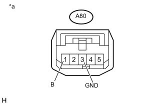
*a Front view of wire harness connector
(to Stop Light Switch Assembly)
Disconnect the A80 stop light switch assembly connector.
-
Measure the voltage according to the value(s) in the table below.
Standard Voltage Tester Connection Condition Specified Condition A80-1 (B) - Body ground Power switch off 11 to 14 V -
Measure the resistance according to the value(s) in the table below.
Standard Resistance Tester Connection Condition Specified Condition A80-3 (GND) - Body ground Always Below 1 Ω
-
-
w/ Dynamic Radar Cruise Control System
-
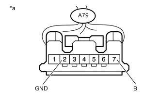
*a Front view of wire harness connector
(to Stop Light Switch Assembly)
Disconnect the A79 stop light switch assembly connector.
-
Measure the voltage according to the value(s) in the table below.
Standard Voltage Tester Connection Condition Specified Condition A79-7 (B) - Body ground Power switch off 11 to 14 V -
Measure the resistance according to the value(s) in the table below.
Standard Resistance Tester Connection Condition Specified Condition A79-2 (GND) - Body ground Always Below 1 Ω
-
NG
REPAIR OR REPLACE HARNESS OR CONNECTOR
OK
-
-
CHECK HARNESS AND CONNECTOR (CERTIFICATION ECU - STOP LIGHT SWITCH ASSEMBLY)
-
Disconnect the A79*1 or A80*2 stop light switch assembly connector.
-

Text in Illustration *a Rear view of wire harness connector
(to Certification ECU (Smart Key ECU Assembly))
Measure the resistance according to the value(s) in the table below.
Standard Resistance Tester Connection Condition Specified Condition L195-18 (STP1) - A79-1 (OUT)*1 Always Below 1 Ω L195-18 (STP1) - A80-2 (OUT)*2 Always Below 1 Ω L195-18 (STP1) or A79-1 (OUT) - Body ground*1 Always 10 kΩ or higher L195-18 (STP1) or A80-2 (OUT) - Body ground*1 Always 10 kΩ or higher -
Reconnect the A79*1 or A80*2 stop light switch assembly connector.
-
Measure the voltage according to the value(s) in the table below.
Standard Voltage Tester Connection Condition Specified Condition L195-18 (STP1) - Body ground Brake pedal released 1 V or less Brake pedal depressed 9 V or higher
-
*1: w/ Dynamic Radar Cruise Control System
-
*2: w/o Dynamic Radar Cruise Control System
-
NG
REPAIR OR REPLACE HARNESS OR CONNECTOR
OK
-
-
INSPECT STOP LIGHT SWITCH ASSEMBLY
-
Inspect the stop light switch assembly Click here.
OK
REPLACE CERTIFICATION ECU (SMART KEY ECU ASSEMBLY)
NG
REPLACE STOP LIGHT SWITCH ASSEMBLY
-