CANISTER(w/o Canister Pump Module) INSTALLATION
PROCEDURE
-
INSTALL CANISTER (CHARCOAL CANISTER ASSEMBLY) (w/o Differential Pressure Sensor)
-
Engage the clip and install the canister (charcoal canister assembly) to the vehicle body and guide with the 3 nuts.
- Torque:
- 5.5 N*m { 56 kgf*cm, 49 in.*lbf }
-
Engage the clamp and connect the outlet charcoal canister tube sub-assembly.
-
Connect the outlet charcoal canister tube sub-assembly to the canister (charcoal canister assembly) and slide the clip to secure it.
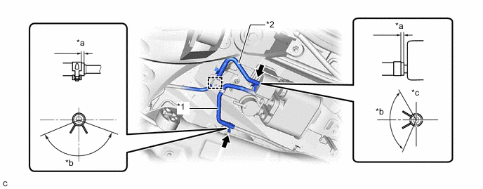
*1 Charcoal Canister Hose *2 Outlet Charcoal Canister Tube Sub-assembly *a 2 to 7 mm (0.0787 to 0.276 in.) *b 120° *c Upper - - -
Connect the charcoal canister hose to the fuel tube and slide the clip to secure it.
Tech Tips
Engage the clip within the area shown in the illustration.
-
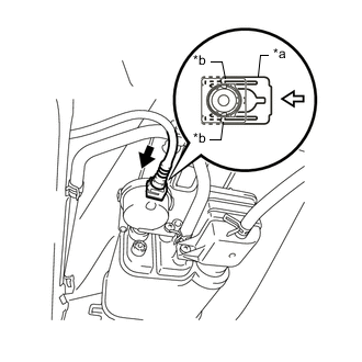
*a Retainer *b Claw 
Push 
Push in Push the fuel tank vent hose sub-assembly onto the canister (charcoal canister assembly) and push in the retainer to engage the 2 claws.
Note
-
Check that there are no scratches or foreign matter around the connecting parts of the fuel tank vent hose sub-assembly and pipe (canister (charcoal canister assembly)) before performing this work.
-
After connecting the fuel tank vent hose sub-assembly, check that the fuel tank vent hose sub-assembly is securely connected by pulling on the tube connector.
-
-
-
INSTALL CANISTER (CHARCOAL CANISTER ASSEMBLY) (w/ Differential Pressure Sensor)
-
Engage the clip and install the canister (charcoal canister assembly) to the vehicle body and guide with the 3 nuts.
- Torque:
- 5.5 N*m { 56 kgf*cm, 49 in.*lbf }
-
Engage the clamp and connect the outlet charcoal canister tube sub-assembly.
-
Connect the outlet charcoal canister tube sub-assembly to the canister (charcoal canister assembly) and slide the clip to secure it.
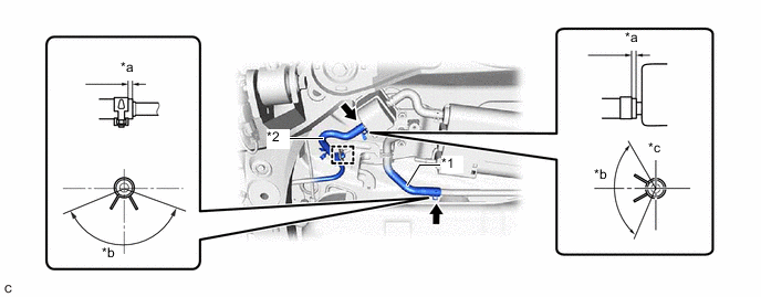
*1 Charcoal Canister Hose *2 Outlet Charcoal Canister Tube Sub-assembly *a 2 to 7 mm (0.0787 to 0.276 in.) *b 120° *c Upper - - -
Connect the charcoal canister hose to the fuel tube and slide the clip to secure it.
Tech Tips
Engage the clip within the area shown in the illustration.
-
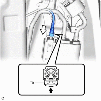
*a Retainer Push Push in Push the fuel tank vent hose sub-assembly onto the canister (charcoal canister assembly) and push in the retainer.
Note
-
Confirm that the retainer makes a "click" sound when pushed.
-
Check that there are no scratches or foreign matter around the connecting parts of the fuel tank vent hose sub-assembly and pipe (canister (charcoal canister assembly)) before performing this work.
-
After connecting the fuel tank vent hose sub-assembly, check that the fuel tank vent hose sub-assembly is securely connected by pulling on the tube connector.
-
-
-
INSTALL CHARCOAL CANISTER PROTECTOR
-
w/o Differential Pressure Sensor:
-
Install the charcoal canister protector with the 3 bolts.
- Torque:
- 5.5 N*m { 56 kgf*cm, 49 in.*lbf }
-
-
w/ Differential Pressure Sensor:
-
Install the charcoal canister protector with the 4 bolts and 3 nuts.
- Torque:
- 5.5 N*m { 56 kgf*cm, 49 in.*lbf }
-
-
-
INSTALL TAIL EXHAUST PIPE ASSEMBLY
-
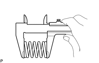
Using a vernier caliper, measure the free length of the compression spring.
Standard length 43.0 mm (1.69 in.) Minimum Free Length 41.5 mm (1.63 in.) If the free length is less than the minimum, replace the compression spring.
-
Temporarily install a new exhaust pipe gasket to the center exhaust pipe assembly.
-
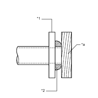
*1 Center Exhaust Pipe Assembly *2 Exhaust Pipe Gasket *a Wooden Block Using a plastic hammer and wooden block, tap in the exhaust pipe gasket until its surface is flush with the center exhaust pipe assembly.
Note
-
Be sure to install the exhaust pipe gasket in the correct direction.
-
Do not reuse the exhaust pipe gasket.
-
Do not damage the exhaust pipe gasket.
-
Do not push in the exhaust pipe gasket by using the exhaust pipes when connecting them.
-
-
Install a new exhaust pipe gasket to the tail exhaust pipe assembly.
-
Connect the tail exhaust pipe assembly to the 2 exhaust pipe supports.
-
Install the tail exhaust pipe assembly to the center exhaust pipe assembly with the 2 bolts and 2 compression springs.
- Torque:
- 43 N*m { 438 kgf*cm, 32 ft.*lbf }
Tech Tips
After installation, check that the space between the flanges of the center exhaust pipe assembly and tail exhaust pipe assembly is consistent front-to-rear and left-to-right.
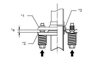
*1 Tail Exhaust Pipe Assembly *2 Center Exhaust Pipe Assembly *3 Exhaust Pipe Gasket *a Space between Flanges: 8.5 mm (0.335 in.) -
Install the tail exhaust pipe assembly to the No. 2 tail exhaust pipe assembly with the 2 bolts.
- Torque:
- 55 N*m { 561 kgf*cm, 41 ft.*lbf }
-
-
INSPECT FOR EXHAUST GAS LEAK