STOP AND START SYSTEM(for 3ZR-FAE) Starter Inrush Current Reduction Relay Circuit
| DTC Code | DTC Name |
|---|---|
| Starter Inrush Current Reduction Relay Circuit |
DESCRIPTION
The starter inrush current reduction relay prevents the battery voltage from becoming dropping excessively while the starter assembly is operating. If the battery voltage drops below the threshold, stop and start control will be prohibited. In order to prevent this, the engine stop and start ECU operates the starter inrush current reduction relay for approximately 0.1 seconds after the ST NO. 2 relay is activated. By allowing current to flow to the starter inrush current reduction relay, the current that flows to the starter motor is reduced, preventing the battery voltage from dropping excessively.
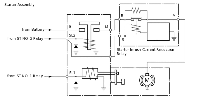
WIRING DIAGRAM
CAUTION / NOTICE / HINT
Starter inrush current reduction relay stuck on:
When the engine is started by stop and start control, a large amount of current will flow to the starter assembly, the battery voltage will drop excessively and stop and start control will be canceled.
Starter inrush current reduction relay stuck off:
Operating current will always flow through the starter inrush current reduction relay and the cranking speed will be low.
PROCEDURE
CHECK WAVEFORM (STARTER INRUSH CURRENT REDUCTION RELAY)
Connect the GTS to the DLC3.
Turn the ignition switch to ON.
Turn the GTS on.
Enter the following menus: Powertrain / Stop and Start / Active Test / Starter Motor Drive Magnet Switch / Data List / Min Volt(After Cranking).
Select the Data List item "Min Volt(After Cranking)".
Powertrain > Stop and Start > Active Test
Active Test Display
Starter Motor Drive Magnet Switch
Data List Display
Min Volt(After Cranking)
Connect the positive (+) lead of an oscilloscope to the positive (+) battery terminal and the negative (-) lead to the negative (-) battery terminal.
While performing the Active Test "Starter Motor Drive Magnet Switch" to forcibly operate the starter motor, count the number of times the waveform drops and check the Data List item "Min Volt(After Cranking)".
Note:The Active Test "Starter Motor Drive Magnet Switch" is stopped automatically after the starter motor operates for 3 seconds.
Do not forcibly operate the starter pinion.
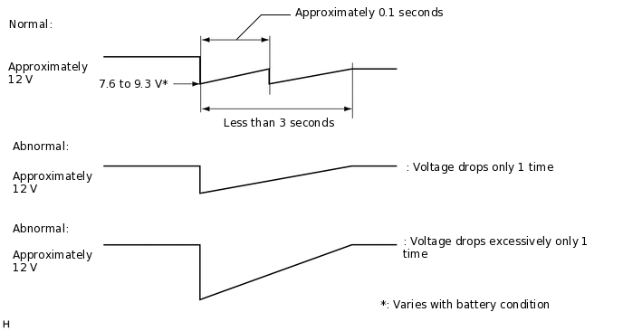
Standard
Specified battery
The voltage waveform has 2 peaks and the "Min Volt (After Cranking)" Data List item (the minimum voltage after the starter begins operation) is 7.66 V or higher
Non-specified battery
The voltage waveform has 2 peaks and the "Min Volt (After Cranking)" Data List item (the minimum voltage after the starter begins operation) is 8.92 V or higher
Result
Number of Times Waveform Dropped
Min Volt(After Cranking) (Data List Item)
Proceed to
2 times
7.66 V or higher*1, 8.92 V or higher*2
A
2 times
Below 7.66 V*1, Below 8.92 V*2
B
Less than 2 times
7.66 V or higher*1, 8.92 V or higher*2
C
Less than 2 times
Below 7.66 V*1, Below 8.92 V*2
D
*1: Specified battery
*2: Non-specified battery
D REPLACE AND CHECK BATTERY
CHECK WAVEFORM (BATTERY VOLTAGE WHEN STARTER ASSEMBLY OPERATED)
Enter the following menus: Powertrain / Stop and Start / Active Test / Starter Motor Drive Magnet Switch.
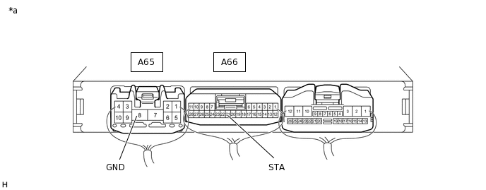
Connect the positive (+) lead of an oscilloscope to the positive (+) battery terminal and the negative (-) lead to the negative (-) battery terminal. Also connect the oscilloscope to terminals A66-21 (STA) and A65-8 (GND) of the stop and start ECU.
*a
Component with harness connected
(Engine Stop and Start ECU)
-
-
While performing the Active Test "Starter Motor Drive Magnet Switch" to forcibly operate the starter motor, measure the battery voltage.
Note:The Active Test "Starter Motor Drive Magnet Switch" is stopped automatically after the starter motor operates for 3 seconds.
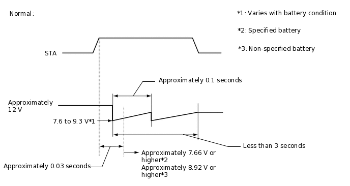
Standard
Specified battery
The minimum voltage immediately after cranking is 7.66 V or higher and the voltage approximately 0.03 seconds after the ST NO. 1 relay is turned ON is approximately 7.65 V or higher
Non-specified battery
The minimum voltage immediately after cranking is 8.92 V or higher and the voltage approximately 0.03 seconds after the ST NO. 1 relay is turned ON is approximately 8.92 V or higher
Tip:Check the value of the following Data List items at the same time.
Data List [Min Voltage(Cranking)]: 7.65 V or higher*1, 8.92 V or higher*2
Data List [Min Volt(After Cranking)]: 7.66 V or higher*1, 8.92 V or higher*2
*1: Specified battery
*2: Non-specified battery
Result
Proceed to
OK
NG