ECD SYSTEM(w/ Glow Plug Controller), Diagnostic DTC:P0016
| DTC Code | DTC Name |
|---|---|
| P0016 | Crankshaft Position - Camshaft Position Correlation (Bank 1 Sensor A) |
DESCRIPTION
Refer to DTC P0340.
DTC No. |
Detection Item |
DTC Detection Condition |
Trouble Area |
MIL |
Memory |
|---|---|---|---|---|---|
P0016 |
Crankshaft Position - Camshaft Position Correlation (Bank 1 Sensor A) |
Phase deviation in crankshaft and camshaft position sensor signals with an engine speed of 650 to 3000 rpm occurs a certain number of times (1 trip detection logic). |
|
Comes on |
DTC Stored |
DTC No. |
DTC Detection Drive Pattern |
|---|---|
P0016 |
Idle engine for 1 second |
If DTC P0016 is stored, the following symptoms may appear:
-
Difficulty starting
Misfire
Combustion noise
Black smoke
White smoke
Lack of power
WIRING DIAGRAM
Refer to DTC P0335.
CAUTION / NOTICE / HINT
After performing the inspection procedure for the camshaft position sensor, if DTC P0016 is output again, check the following items related to the crankshaft position sensor.
-
Installation condition of the crankshaft position sensor
No. 1 crankshaft position sensor plate
Connection of the crankshaft position sensor connector
Read freeze frame data using the GTS. Freeze frame data records the engine condition when malfunctions are detected. When troubleshooting, freeze frame data can help determine if the vehicle was moving or stationary, if the engine was warmed up or not, and other data from the time the malfunction occurred.
PROCEDURE
CHECK HARNESS AND CONNECTOR (CAMSHAFT POSITION SENSOR - ECM)
Disconnect the camshaft position sensor connector.
Disconnect the ECM connector.
Measure the resistance according to the value(s) in the table below.
Standard Resistance
Tester Connection
Condition
Specified Condition
B117-3 (VG) - B212-68 (VCG)
Always
Below 1 Ω
B117-1 (G1) - B212-83 (G+)
Always
Below 1 Ω
B117-2 (G-) - B212-115 (G-)
Always
Below 1 Ω
B117-3 (VG) or B212-68 (VCG) - Body ground and other terminals
Always
10 kΩ or higher
B117-1 (G1) or B212-83 (G+) - Body ground and other terminals
Always
10 kΩ or higher
B117-2 (G-) or B212-115 (G-) - Body ground and other terminals
Always
10 kΩ or higher
Result
Proceed to
OK
NG
NG REPAIR OR REPLACE HARNESS OR CONNECTORClick here
CHECK TERMINAL VOLTAGE (POWER SOURCE OF CAMSHAFT POSITION SENSOR)
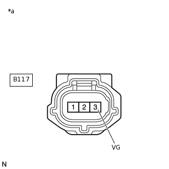
*a
Front view of wire harness connector
(to Camshaft Position Sensor)
Disconnect the camshaft position sensor connector.
Turn the ignition switch to ON.
Measure the voltage according to the value(s) in the table below.
Standard Voltage
Tester Connection
Condition
Specified Condition
B117-3 (VG) - Body ground
Ignition switch ON
4.5 to 5.5 V
Result
Proceed to
OK
NG
NG REPLACE ECMClick here
CHECK SENSOR INSTALLATION (CAMSHAFT POSITION SENSOR)
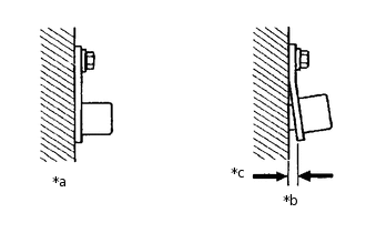
*a
OK
*b
NG
*c
Clearance
Check the camshaft position sensor installation.
OK
Sensor is installed correctly.
Result
Proceed to
OK
NG
NG SECURELY REINSTALL CAMSHAFT POSITION SENSORClick here
CHECK CRANKSHAFT POSITION SENSOR PLATE
Check the condition of the crankshaft position sensor plate.
OK
Crankshaft position sensor plate does not have any cracks or deformation.
Result
Proceed to
OK
NG
NG REPLACE CRANKSHAFT POSITION SENSOR PLATEClick here
CHECK HARNESS AND CONNECTOR (CRANKSHAFT POSITION SENSOR CIRCUIT)
Connect the GTS to the DLC3.
Turn the ignition switch to ON.
Turn the GTS on.
Clear the DTCs.
Powertrain > Engine and ECT > Clear DTCs
Turn the ignition switch off and wait for 30 seconds or more.
Start the engine and idle it for 4 seconds or more.
Turn the GTS on.
Check the engine condition while wiggling the crankshaft position sensor wire harness for 4 seconds or more when idling.
Enter the following menus: Powertrain / Engine and ECT / Trouble Codes.
Read the DTCs.
Powertrain > Engine and ECT > Trouble Codes
Result
Result
Proceed to
Except below
A
There are problem such as rough idle or engine stall when wire harness is wiggles, or DTC is output*
B
Tip:*: As the DTC was stored due to a change in the contact resistance of the connector, repair or replace the wire harness or connector.
B CONFIRM WHETHER MALFUNCTION HAS BEEN SUCCESSFULLY REPAIREDClick here
REPLACE CAMSHAFT POSITION SENSOR
Replace the camshaft position sensor.
Result
Proceed to
NEXT
CHECK WHETHER DTC OUTPUT RECURS
Connect the GTS to the DLC3.
Turn the ignition switch to ON.
Turn the GTS on.
Clear the DTCs.
Powertrain > Engine and ECT > Clear DTCs
Turn the ignition switch off for 30 seconds or more.
Start the engine and idle it for 4 seconds or more.
Enter the following menus: Powertrain / Engine and ECT / Trouble Codes.
Read the DTCs.
Powertrain > Engine and ECT > Trouble Codes
Result
Result
Proceed to
DTC P0016 is output
A
DTC is not output
B
B END
REPLACE ECM
Replace the ECM.
Result
Proceed to
NEXT
NEXT CONFIRM WHETHER MALFUNCTION HAS BEEN SUCCESSFULLY REPAIREDClick here
REPLACE CRANKSHAFT POSITION SENSOR PLATE
Replace the crankshaft position sensor plate.
Result
Proceed to
NEXT
NEXT CONFIRM WHETHER MALFUNCTION HAS BEEN SUCCESSFULLY REPAIREDClick here
SECURELY REINSTALL CAMSHAFT POSITION SENSOR
Securely reinstall the camshaft position sensor.
Result
Proceed to
NEXT
NEXT CONFIRM WHETHER MALFUNCTION HAS BEEN SUCCESSFULLY REPAIREDClick here
REPAIR OR REPLACE HARNESS OR CONNECTOR
Result
Proceed to
NEXT
CONFIRM WHETHER MALFUNCTION HAS BEEN SUCCESSFULLY REPAIRED
Connect the GTS to the DLC3.
Turn the ignition switch to ON.
Turn the GTS on.
Clear the DTCs.
Powertrain > Engine and ECT > Clear DTCs
Turn the ignition switch off for 30 seconds or more.
Start the engine and idle it for 4 seconds or more.
Enter the following menus: Powertrain / Engine and ECT / Trouble Codes.
Confirm that the DTC is not output.
Powertrain > Engine and ECT > Trouble Codes
Result
Proceed to
NEXT
NEXT END