CYLINDER BLOCK INSPECTION
PROCEDURE
INSPECT NO. 1 OIL NOZZLE SUB-ASSEMBLY
Check the No. 1 oil nozzle sub-assembly for damage or clogging.
If there is damage or clogging, replace the No. 1 oil nozzle sub-assembly.
CLEAN CYLINDER BLOCK
Using a gasket scraper, remove all the gasket material from the top surface of the cylinder block.
Using a soft brush and solvent, thoroughly clean the cylinder block.
INSPECT CYLINDER BORE
-
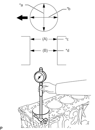
Using a cylinder gauge, measure the cylinder bore diameter at positions A and B in the thrust and axial directions.
Reference Value (New Parts)
Item
Specified Condition
STD
78.000 to 78.002 mm (3.0708 to 3.0709 in.)
O/S 0.25
78.250 to 78.252 mm (3.0807 to 3.0808 in.)
Table 1. Text in Illustration *a
Thrust Direction
*b
Axial Direction
*c
Upper
*d
Center

Front
-
CLEAN PISTON
Using a gasket scraper, remove the carbon from the piston top.
Using a groove cleaning tool or broken ring, clean the piston ring grooves.
Using solvent and a brush, thoroughly clean the piston sub-assembly.
Note:Do not use a wire brush.
INSPECT PISTON DIAMETER
-
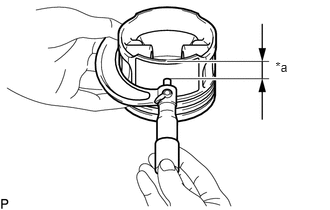
Using a micrometer, measure the piston diameter at right angles to the piston center line where the position is 13 mm (0.511 in.) from the bottom edge of the piston sub-assembly.
Reference Value (New Parts)
Item
Specified Condition
STD
77.950 to 77.970 mm (3.0689 to 3.0697 in.)
O/S 0.25
78.200 to 78.220 mm (3.0787 to 3.0795 in.)
Table 2. Text in Illustration *a
13 mm (0.511 in.)
-
INSPECT PISTON OIL CLEARANCE
Measure the cylinder bore diameter in the thrust direction.
Subtract the piston diameter measurement from the cylinder bore diameter measurement.
Reference Value (New Parts)
Item
Specified Condition
New Piston
0.03 to 0.17 mm (0.00118 to 0.00669 in.)
Used Piston
0.20 to 0.25 mm (0.00787 to 0.00984 in.)
Maximum oil clearance
More than 0.25 mm (0.00984 in.)
If the oil clearance is more than the standard, replace the piston with pin sub-assembly.
INSPECT RING GROOVE CLEARANCE
Using a feeler gauge, measure the clearance between a new piston ring and the wall of the ring groove.
Standard Ring Groove Clearance
Ring
Specified Condition
No. 1 Compression Ring
0.015 to 0.070 mm (0.00059 to 0.00276 in.)
No. 2 Compression Ring
0.015 to 0.060 mm (0.00059 to 0.00236 in.)
Oil Ring Rail
0.04 to 0.10 mm (0.00157 to 0.00394 in.)
If the clearance is more than the standard, replace the piston with pin sub-assembly.
INSPECT PISTON RING END GAP
Insert the piston ring into the cylinder bore.
Using a feeler gauge, measure the end gap.
Standard End Gap
Ring
Specified Condition
No. 1 Compression Ring
0.20 to 0.40 mm (0.00787 to 0.0157 in.)
No. 2 Compression Ring
0.30 to 0.55 mm (0.0118 to 0.0217 in.)
Oil Ring Rail
0.10 to 0.40 mm (0.00394 to 0.0157 in.)
Maximum End Gap
Ring
Specified Condition
No. 1 Compression Ring
0.95 mm (0.0374 in.)
No. 2 Compression Ring
1.06 mm (0.0417 in.)
Oil Ring Rail
0.82 mm (0.0322 in.)
If the end gap is more than the maximum, replace the piston ring. If the end gap is more than the maximum even with a new piston ring set, replace the piston with pin sub-assembly.
INSPECT CRANKSHAFT OIL CLEARANCE
Install the crankshaft bearing (Click here).
Clean each main journal and bearing.
Check each main journal and bearing for pitting and scratches.
If the journal or bearing is damaged, replace the crankshaft bearing.
Place the crankshaft assembly on the cylinder block.
-
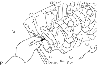
Lay a strip of Plastigage across each journal.
Table 3. Text in Illustration *a
Plastigage
Install the crankshaft bearing caps (Click here).
Note:Do not turn the crankshaft assembly.
Remove the crankshaft bearing cap.
-
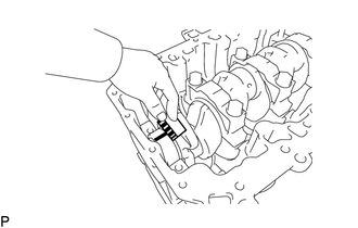
Measure the Plastigage at its widest point.
Standard oil clearance
0.023 to 0.054 mm (0.000905 to 0.00212 in.)
Tip:Check the code mark on the upper crankshaft bearing side and lower crankshaft bearing side, and then select the bearing size.
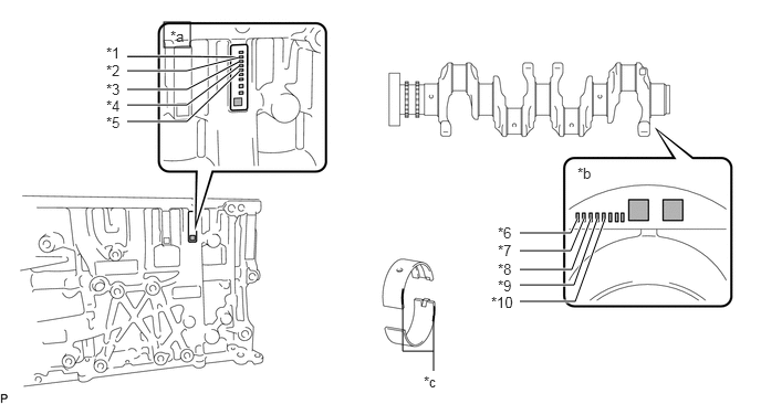
Table 4. Text in Illustration *1
No. 1 Upper Crankshaft Bearing
*2
No. 2 Upper Crankshaft Bearing
*3
No. 3 Upper Crankshaft Bearing
*4
No. 4 Upper Crankshaft Bearing
*5
No. 5 Upper Crankshaft Bearing
*6
No. 1 Lower Crankshaft Bearing
*7
No. 2 Lower Crankshaft Bearing
*8
No. 3 Lower Crankshaft Bearing
*9
No. 4 Lower Crankshaft Bearing
*10
No. 5 Lower Crankshaft Bearing
*a
Upper Crankshaft Bearing Side Code Mark
*b
Lower Crankshaft Bearing Side Code Mark
*c
Color
-
-
Table 5. Bearing Chart Upper Crankshaft Bearing Side Code Mark / Lower Crankshaft Bearing Side Code Mark
Upper Crankshaft Bearing Color
Lower Crankshaft Bearing Color
1 / 1
Yellow
Yellow
1 / 2
Yellow
Green
1 / 3
Yellow
White
2 / 1
Green
Yellow
2 / 2
Green
Green
2 / 3
Green
White
3 / 1
White
Yellow
3 / 2
White
Green
3 / 3
White
White
Reference
Cylinder Block Main Bearing Journal Diameter
Table 6. Standard Bearing Item
Specified Condition
Mark 1
54.984 to 54.990 mm (2.16472 to 2.16495 in.)
Mark 2
54.977 to 54.983 mm (2.16444 to 2.16468 in.)
Mark 3
54.971 to 54.976 mm (2.16420 to 2.16440 in.)
Table 7. U/S 0.25 Bearing Item
Specified Condition
Mark 1
54.734 to 54.740 mm (2.15487 to 2.15511 in.)
Mark 2
54.727 to 54.733 mm (2.15460 to 2.15483 in.)
Mark 3
54.721 to 54.726 mm (2.15436 to 2.15456 in.)
Completely remove the Plastigage.
Lift out the crankshaft assembly.
Remove the crankshaft bearing (Click here).