EMISSION CONTROL SYSTEM
-
FUNCTION OF MAIN COMPONENTS
-
The main components of the 2ZR-FXE emission control system are as follows:
Component Function TWC Oxidizes CO and HC in the exhaust gas and deoxidizes NOx at the same time, to purify them into CO2, H2O and N2. Oxygen Sensor This sensor detects the oxygen concentration in the exhaust emission by measuring the electromotive force which is generated in the sensor itself. Air Fuel Ratio Sensor As with the oxygen sensor, this sensor detects the oxygen concentration in the exhaust gas. However, it detects the oxygen concentration in the exhaust gas linearly. E. F. I. Vacuum Sensor Assembly Uses built-in semiconductors to detect the intake manifold pressure. EGR Valve Assembly Operates when receiving signals from the ECM, regulating the EGR volume. EGR Cooler Cools the exhaust gas temperature to improve the EGR efficiency. PCV Valve Opens and closes using vacuum generated in the intake manifold and controls the flow rate of the blowby gas. Charcoal Canister Contains activated charcoal to absorb the fuel vapors that are created in the fuel tank assembly. Purge VSV Opens in accordance with the signals from the ECM when the system is purging, in order to send the fuel vapor that was absorbed by the charcoal canister into the intake manifold. ECM
-
Controls the volume of fuel injected, with corrections based primarily on the signal from the air fuel ratio sensor, and minor corrections based on the signal from the oxygen sensor. This control optimizes the air fuel ratio.
-
Regulates the EGR volume in accordance with the various sensor signals.
-
Controls the purge VSV in accordance with the signals from various sensors, in order to achieve a purge volume that suits the driving conditions.
-
-
-
SYSTEM CONTROL
-
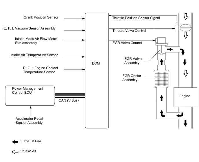
EGR Control
-
For the EGR system, a regulated amount of inert gas is allowed to flow into the intake passage, reducing the peak temperature in the engine combustion chamber.
-
By sensing the engine driving conditions and actual amount of the EGR valve opening, the ECM operates the EGR valve and throttle control motor, to regulate the amount of exhaust gas that is recirculated.
-
-
Blowby Gas Ventilation System
-
By introducing blowby gas that has a large amount of HC into the intake manifold for combustion, the system enhances the emission performance. The amount of airflow through the crankcase (blowby gas introduction volume) is controlled according to the engine operating conditions. This prevents the excessive consumption of engine oil, and is a factor in idle speed control.
-
An oil separator is provided in the blowby gas passage inside the cylinder block sub-assembly. This separates the engine oil from the blowby gas in order to reduce oil degradation and reduce the amount of engine oil consumed.
-
The Positive Crankcase Ventilation (PCV) valve passage returns the blowby gas into the area after the throttle valve in accordance with the intake manifold vacuum.
-
When engine load is low, the intake manifold vacuum draws gases from the crankcase via the PCV valve, oil separator and hose. Fresh air is supplied to the crankcase to replace the gases drawn in through the PCV valve. The passage from the area before the throttle to the cylinder head cover supplies this fresh air to the crankcase.
-
When engine load is high, some of the gases in the crankcase (including blowby gas) are supplied to the intake manifold from the crankcase via the PCV valve, oil separator and hose, and the remaining gases are transferred via the passage from the cylinder head cover to the area before the throttle.
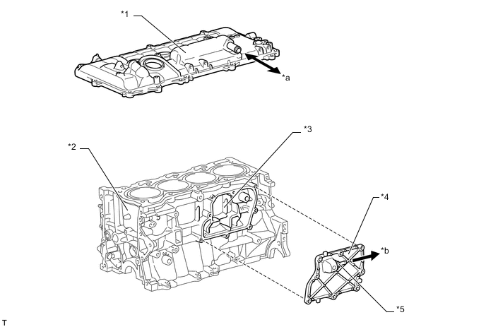
Text in Illustration *1 Cylinder Head Cover Sub-assembly *2 Cylinder Block Sub-assembly *3 Oil Separator *4 Oil Separator Cover
(No. 1 Ventilation Case)
*5 PCV Valve - - *a To Air Cleaner Hose *b To Intake Manifold 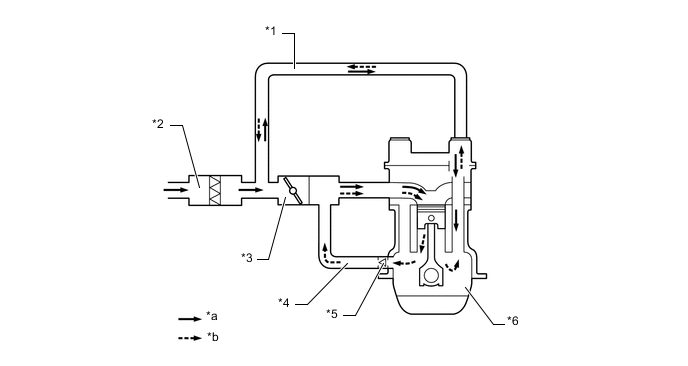
Text in Illustration *1 No. 2 Ventilation Hose *2 Air Cleaner Case *3 Throttle Body *4 No. 1 Ventilation Hose *5 PCV Valve *6 Crankcase *a Fresh Air *b Blowby Gas
-
-
-
CONSTRUCTION
-
Three-Way Catalytic Converter (TWC)
-
2 TWCs are provided at the front of the front exhaust pipe assembly.
-
These TWCs enable improved exhaust emissions with an optimized cell density and wall thickness.
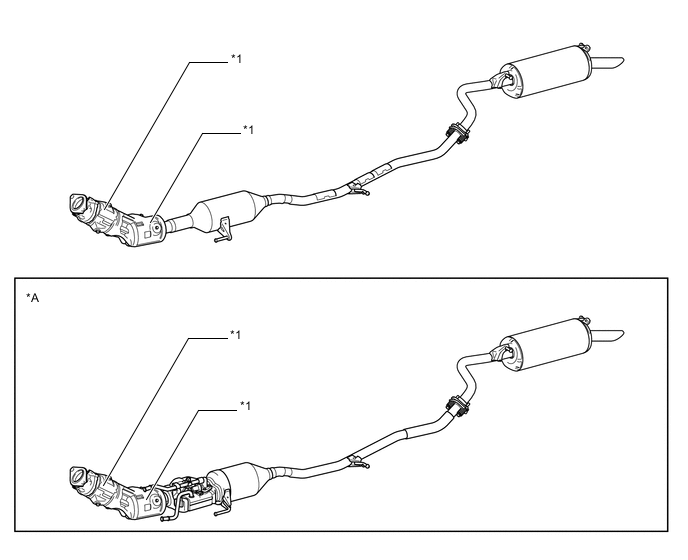
Text in Illustration *A Cold Area Specification Models - - *1 TWC - -
-
-
EGR Valve and EGR Cooler
-
A step motor type EGR valve assembly is used to precisely control the EGR gas flow amount.
-
The EGR cooler cools the exhaust gas to improve the EGR efficiency.
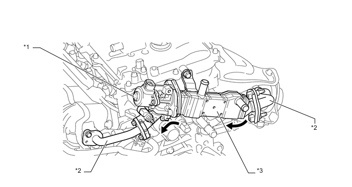
Text in Illustration *1 EGR Valve Assembly *2 EGR Pipe *3 EGR Cooler - - 
EGR Gas - -
-
-
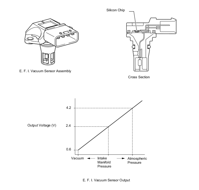
E. F. I. Vacuum Sensor Assembly
-
An E. F. I. vacuum sensor assembly is used to measure the intake manifold pressure for the EGR control.
-
The E. F. I. vacuum sensor assembly consists of a silicon chip which utilizes the characteristics of a silicon chip that changes its electrical resistance when pressure is applied to it. The sensor converts the pressure into an electrical signal, and sends it to the ECM in an amplified form.
-
-