SLIDING ROOF HOUSING(for Panoramic Moon Roof) REASSEMBLY
PROCEDURE
-
INSTALL SUNSHADE TRIM SUB-ASSEMBLY
-
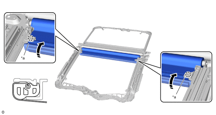
Attach the stopper and press it down in the direction of the arrow (1) shown in the illustration. Then, insert the retractor cap to install the sunshade trim sub-assembly.
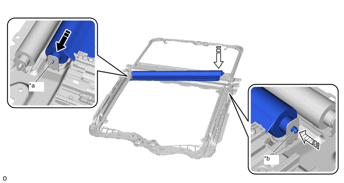
*a Stopper *b Retractor Cap 
Attach the stopper 
Install in this Direction (1) 
Insert retractor cap - - -
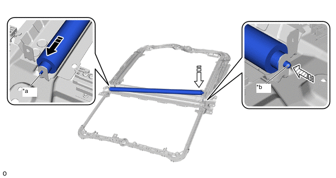
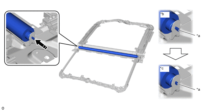
Insert the stopper to release the sunshade trim sub-assembly lock as shown in the illustration.
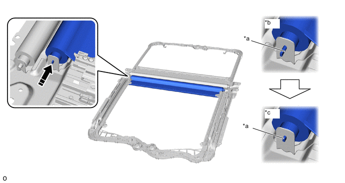
*a Stopper *b Lock *c Unlock - - Push in this direction - - -
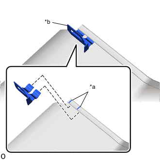
*a String *b Clip Install the clip to the sunshade trim sub-assembly as shown in the illustration.
Tech Tips
Use the same procedure for the other side.
-
Install the clip and sunshade trim sub-assembly in the direction shown in the illustration.
Tech Tips
Use the same procedure for the other side.
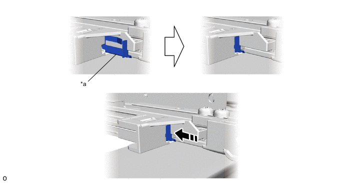
*a Clip - - Install in this Direction - - -
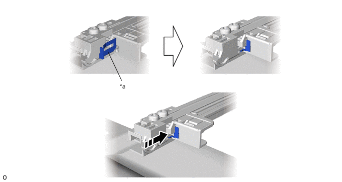
Install as shown in the illustration.
Tech Tips
Use the same procedure for the other side.

Clip - - -
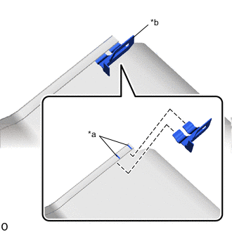
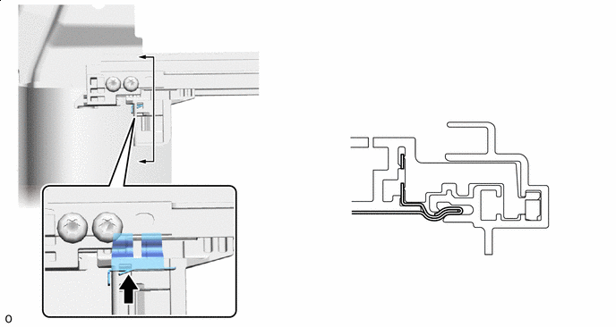
Attach the claw and install part A as shown in the illustration.
*a Part A - - Install in this Direction - -
-
-
INSTALL NO. 2 SUNSHADE TRIM SUB-ASSEMBLY
-
Attach the stopper and press it down in the direction of the arrow (1) shown in the illustration. Then, insert the retractor cap to install the No. 2 sunshade trim sub-assembly.
*a Stopper *b Retractor Cap Attach the stopper Install in this Direction (1) Insert retractor cap - - -
Insert the stopper to release the No. 2 sunshade trim sub-assembly lock as shown in the illustration.
*a Stopper *b Lock *c Unlock - - Push in this Direction - - -
*a String *b Clip Install the clip to the No. 2 sunshade trim sub-assembly as shown in the illustration.
Tech Tips
Use the same procedure for the other side.
-
Install the clip and No. 2 sunshade trim sub-assembly in the direction shown in the illustration.
Tech Tips
Use the same procedure for the other side.
*a Clip - - Install in this Direction - - -
Install as shown in the illustration.
Tech Tips
Use the same procedure for the other side.
Claw - - -
Attach the claw and install part A as shown in the illustration.
*a Part A - - Install in this Direction - -
-
-
INSTALL SLIDING ROOF DRIVE GEAR ASSEMBLY (for rear roof sunshade)
-
Apply MP grease to the gear of the sliding roof drive gear assembly.
-
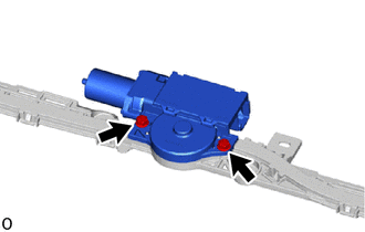
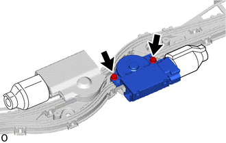
Install the sliding roof drive gear assembly with the 2 bolts.
- Torque:
- 5.4 N*m { 55 kgf*cm, 48 in.*lbf }
-
-
INSTALL SLIDING ROOF HOUSING PAD (for rear roof sunshade)
-
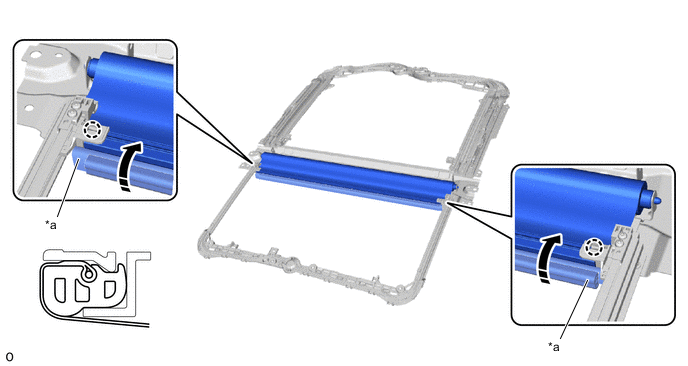
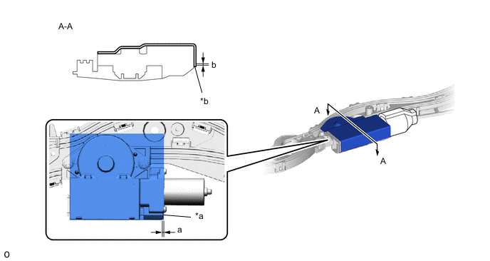
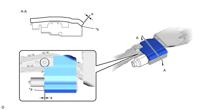
Remove the peeling paper, install the new sliding roof housing pad.
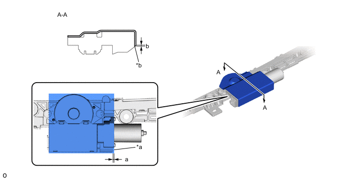
*a Sliding Roof Drive Gear Assembly End (Application Standard Point) *b R End Standard Location Measurement a -1.0 to 1.0 mm (-0.0394 to 0.0394 in.) b 0 to 2.0 mm (0 to 0.0787 in.)
-
-
INSTALL NO. 2 SLIDING ROOF HOUSING PAD (for rear roof sunshade)
-
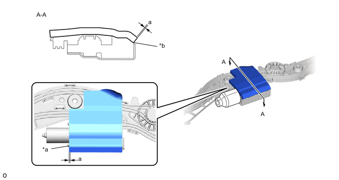
Remove the peeling paper, install the new No. 2 sliding roof housing pad.
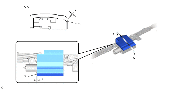
*a Sliding Roof Drive Gear Assembly End (Application Standard Point) *b R End Standard Location Measurement a -1.0 to 1.0 mm (-0.0394 to 0.0394 in.)
-
-
INSTALL SLIDING ROOF DRIVE GEAR ASSEMBLY (for front roof sunshade)
-
Apply MP grease to the gear of the sliding roof drive gear assembly.
-
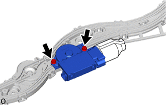
Install the 2 bolts and sliding roof drive gear assembly.
- Torque:
- 5.4 N*m { 55 kgf*cm, 48 in.*lbf }
-
-
INSTALL SLIDING ROOF HOUSING PAD (for front roof sunshade)
-
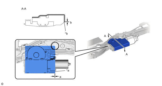
Remove the peeling paper, install the new sliding roof housing pad.
*a Sliding Roof Drive Gear Assembly End (Application Standard Point) *b R End Standard Location Measurement a -1.0 to 1.0 mm (-0.0394 to 0.0394 in.) b 0 to 2.0 mm (0 to 0.0787 in.)
-
-
INSTALL NO. 2 SLIDING ROOF HOUSING PAD (for front roof sunshade)
-
Remove the peeling paper, install the new No. 2 sliding roof housing pad.
*a Sliding Roof Drive Gear Assembly End (Application Standard Point) *b R End Standard Location Measurement a -1.0 to 1.0 mm (-0.0394 to 0.0394 in.)
-
-
INSTALL SLIDING ROOF DRIVE GEAR SUB-ASSEMBLY (for sliding roof)
-
Apply MP grease to the gear of the sliding roof drive gear sub-assembly.
-
Install the 2 bolts and sliding roof drive gear sub-assembly.
- Torque:
- 5.4 N*m { 55 kgf*cm, 48 in.*lbf }
-
-
INSTALL SLIDING ROOF HOUSING PAD (for sliding roof)
-
Remove the peeling paper, install the new sliding roof housing pad.
*a Sliding Roof Drive Gear Assembly End (Application Standard Point) *b R End Standard Location Measurement a -1.0 to 1.0 mm (-0.0394 to 0.0394 in.) b 0 to 2.0 mm (0 to 0.0787 in.)
-
-
INSTALL NO. 2 SLIDING ROOF HOUSING PAD (for sliding roof)
-
Remove the peeling paper, install the new No. 2 sliding roof housing pad.
*a Sliding Roof Drive Gear Assembly End (Application Standard Point) *b R End Standard Location Measurement a -1.0 to 1.0 mm (-0.0394 to 0.0394 in.) -
Install the room light bracket with the 2 screws.
- Torque:
- 1.1 N*m { 11 kgf*cm, 10 in.*lbf }
-
-
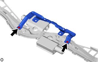
INSTALL NO. 2 ROOF WIRE
-
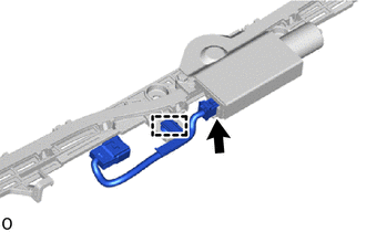
Attach the clamp to install the No. 2 roof wire.
-
Connect the connector.
-
-
INSTALL SLIDING ROOF HOUSING SUB-ASSEMBLY
-
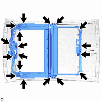
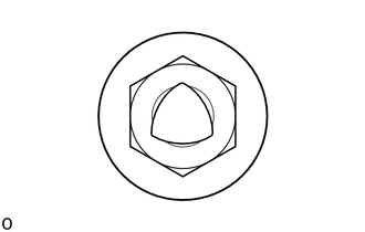
Install the slide roof housing sub-assembly with the 18 nuts.
- Torque:
- 6.3 N*m { 64 kgf*cm, 56 in.*lbf }
Note
If the removed nut is the same shape as that shown in the illustration, replace it the supplied replacement part.
-
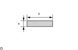

Tape Prepare the 2 sizes of new tape as in indicated the illustration.
Standard Area Specified Condition a 20 mm (0.787 in.) b 90 mm (3.54 in.) -
Install the tape as shown in the illustration.
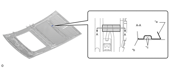
*a Tape Grip Part *b R End *c Wire Harness - - Tape - -
-
-
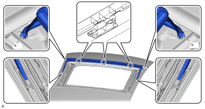
INSTALL ROOF WIND DEFLECTOR PANEL SUB-ASSEMBLY
-
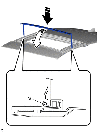
*a Guide Install in this Direction (1) Install in this Direction (2) Attach the guide and install the roof wind deflector panel sub-assembly in the direction indicated by the arrow (1) shown in the illustration.
-
Move the roof wind deflector panel sub-assembly in the direction indicated by the arrow (2) shown in the illustration.
-
Attach the guide.
*a Guide - - -
Attach the claw and install the roof wind deflector panel sub-assembly.
-