AIR CONDITIONING SYSTEM, Diagnostic DTC:B1422
| DTC Code | DTC Name |
|---|---|
| B1422 | Compressor Lock |
DESCRIPTION
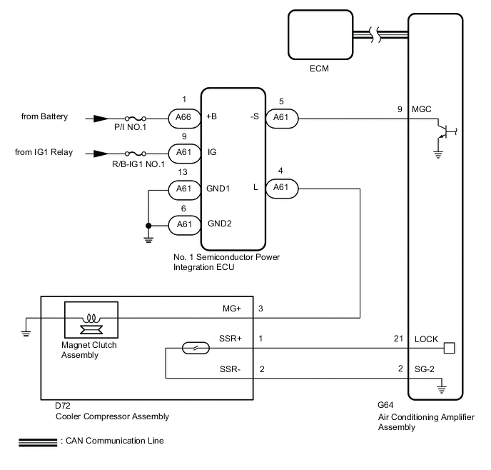
The ECM sends the engine speed signal to the air conditioning amplifier assembly via CAN communication.
The air conditioning amplifier assembly reads the difference between compressor speed and engine speed. When the difference becomes too large, the air conditioning amplifier assembly determines that the compressor is locked, and turns the magnet clutch assembly off.
| DTC No. | Detection Item | DTC Detection Condition | Trouble Area | Memory |
|---|---|---|---|---|
| B1422 | Compressor Lock | Open or short in A/C lock sensor circuit
|
|
Memorized |
Tech Tips
The air conditioning amplifier assembly stores the DTC of the respective malfunction if it has occurred for the period of time indicated in the parentheses.
WIRING DIAGRAM
CAUTION / NOTICE / HINT
Note
-
ECM malfunctions can affect the storage of this DTC. Therefore, check all SFI system DTCs and confirm that the system is normal before performing the following inspection.
-
Inspect the fuses for circuits related to this system before performing the following procedure.
PROCEDURE
-
CHECK CAN COMMUNICATION SYSTEM
-
Using the GTS, check if the CAN communication system is functioning normally.
OK CAN communication system DTCs are not output. Result Proceed to OK NG
NG 
GO TO CAN COMMUNICATION SYSTEM Click here
OK 
-
-
INSPECT COOLER COMPRESSOR ASSEMBLY
-
Remove the cooler compressor assembly.
-
Inspect the cooler compressor assembly.
Result Proceed to OK NG
NG
REPLACE COOLER COMPRESSOR ASSEMBLY Click here
OK
-
-
CHECK HARNESS AND CONNECTOR (COOLER COMPRESSOR ASSEMBLY - AIR CONDITIONING AMPLIFIER ASSEMBLY)
-
Disconnect the D72 cooler compressor assembly connector.
-
Disconnect the G64 air conditioning amplifier assembly connector.
-
Measure the resistance according to the value(s) in the table below.
Standard Resistance Tester Connection Condition Specified Condition D72-1 (SSR+) - G64-21 (LOCK) Always Below 1 Ω D72-2 (SSR-) - G64-2 (SG-2) Always Below 1 Ω D72-1 (SSR+) - D72-2 (SSR-) Always 10 kΩ or higher D72-1 (SSR+) or G64-21 (LOCK) - Other terminals and body ground Always 10 kΩ or higher D72-2 (SSR-) or G64-2 (SG-2) - Other terminals and body ground Always 10 kΩ or higher Result Proceed to OK NG
OK
REPLACE AIR CONDITIONING AMPLIFIER ASSEMBLY Click here
NG
REPAIR OR REPLACE HARNESS OR CONNECTOR
-