SFI SYSTEM(w/ EGR System) ECM Power Source Circuit
| DTC Code | DTC Name |
|---|---|
| ECM Power Source Circuit |
DESCRIPTION
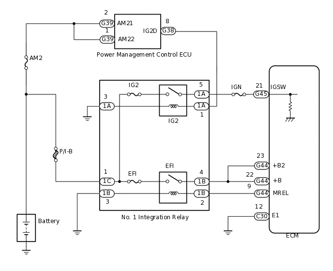
When the engine switch is turned on (IG), the battery voltage is applied to the IGSW terminal of the ECM. The output signal from the MREL terminal of the ECM causes a current to flow to the coil of the No. 1 integration relay (EFI relay), closing the contacts and supplying power to terminals +B and +B2 of the ECM.
WIRING DIAGRAM
CAUTION / NOTICE / HINT
Inspect the fuses for circuits related to this system before performing the following inspection procedure.
PROCEDURE
CHECK NO. 1 INTEGRATION RELAY (POWER SOURCE)
Remove the No. 1 integration relay from the engine room relay block.
-
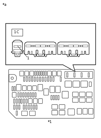
*1
Engine Room Relay Block
*a
Front view of wire harness connector
(to No. 1 Integration Relay)
Measure the voltage according to the value(s) in the table below.
Standard Voltage
Tester Connection
Condition
Specified Condition
1C-1 - Body ground
Always
11 to 14 V
Result
Result
OK
NG
NG REPAIR OR REPLACE HARNESS OR CONNECTOR (NO. 1 INTEGRATION RELAY - BATTERY)
INSPECT NO. 1 INTEGRATION RELAY (EFI)
Inspect the No. 1 integration relay (EFI).
Result
Result
OK
NG
CHECK HARNESS AND CONNECTOR (NO. 1 INTEGRATION RELAY - ECM, BODY GROUND)
Check the harness and connectors between the No. 1 integration relay and ECM.
Remove the No. 1 integration relay from the engine room relay block.
Disconnect the ECM connector.
Measure the resistance according to the value(s) in the table below.
Standard Resistance
Tester Connection
Condition
Specified Condition
G44-9 (MREL) - 1B-2
Always
Below 1 Ω
G44-22 (+B) - 1B-4
Always
Below 1 Ω
G44-23 (+B2) - 1B-4
Always
Below 1 Ω
G44-9 (MREL) or 1B-2 - Body ground
Always
10 kΩ or higher
G44-22 (+B) or 1B-4 - Body ground
Always
10 kΩ or higher
G44-23 (+B2) or 1B-4 - Body ground
Always
10 kΩ or higher
Check the harness and connectors between the No. 1 integration relay and body ground.
Measure the resistance according to the value(s) in the table below.
Standard Resistance
Tester Connection
Condition
Specified Condition
1B-3 - Body ground
Always
Below 1 Ω
Result
Result
OK
NG
NG REPAIR OR REPLACE HARNESS OR CONNECTOR
CHECK HARNESS AND CONNECTOR (ECM - BODY GROUND)
Disconnect the ECM connector.
Measure the resistance according to the value(s) in the table below.
Standard Resistance
Tester Connection
Condition
Specified Condition
C30-12 (E1) - Body ground
Always
Below 1 Ω
Result
Result
OK
NG
NG REPAIR OR REPLACE HARNESS OR CONNECTOR
INSPECT ECM (IGSW VOLTAGE)
-
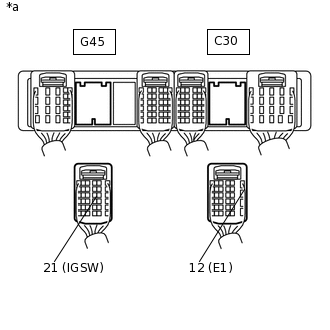
*a
Rear view of wire harness connector
(to ECM)
Disconnect the ECM connectors.
Turn the engine switch on (IG).
Measure the voltage according to the value(s) in the table below.
Standard Voltage
Tester Connection
Switch Condition
Specified Condition
G45-21 (IGSW) - C30-12 (E1)
Engine switch on (IG)
11 to 14 V
Result
Result
OK
NG
-
INSPECT NO. 1 INTEGRATION RELAY (IG2)
Inspect the No. 1 integration relay (IG2).
Result
Result
OK
NG
CHECK HARNESS AND CONNECTOR (NO. 1 INTEGRATION RELAY - ECM)
Remove the No. 1 integration relay from the engine room relay block.
Disconnect the ECM connector.
Measure the resistance according to the value(s) in the table below.
Standard Resistance
Tester Connection
Condition
Specified Condition
1A-5 - G45-21 (IGSW)
Always
Below 1 Ω
1A-5 or G45-21 (IGSW) - Body ground
Always
10 kΩ or higher
Result
Result
Proceed to
Out of normal range
A
Within normal range
B
A REPAIR OR REPLACE HARNESS OR CONNECTOR
CHECK HARNESS AND CONNECTOR (NO. 1 INTEGRATION RELAY - POWER MANAGEMENT CONTROL ECU)
Remove the No. 1 integration relay from the engine room relay block.
Disconnect the power management control ECU connector.
Measure the resistance according to the value(s) in the table below.
Standard Resistance
Tester Connection
Condition
Specified Condition
1A-1 - G38-8 (IG2D)
Always
Below 1 Ω
1A-3 - Body ground
Always
Below 1 Ω
G38-8 (IG2D) - Body ground
Always
10 kΩ or higher
Result
Result
OK
NG
NG REPAIR OR REPLACE HARNESS OR CONNECTOR