FUEL SENDER GAUGE ASSEMBLY INSPECTION

PROCEDURE
-
INSPECT FUEL SENDER GAUGE ASSEMBLY
CAUTION:
Take special care of fire.
-
Inspect to see if there is any damage to the fuel sender gauge assembly.
-
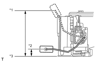
Text in Illustration *1 Float position F (upper end) *2 Float position E (lower end) *3 Fuel tank seat face Measure the dimensions between the fuel tank seat face and the float center with the float position at F (upper end) and at E (lower end).
Dimensions Float position F (upper end) to fuel tank seat face 121 to 129 mm (4.764 to 5.079 in.) Float position E (lower end) to fuel tank seat face 14.7 to 22.7 mm (0.579 to 0.894 in.) -
Check that the float moves smoothly between F (upper) and E (lower).
-
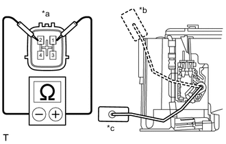
Text in Illustration *a Component without harness connected
(Fuel Sender Gauge Assembly)
*b F (upper end) *c E (lower end) Measure the resistance according to the value(s) in the table below.
Standard Resistance Tester Connection Condition Specified Condition 1 - 2 Float position is F (upper end) 6.5 to 8.5 Ω Float position is E (lower end) 168 to 172 Ω If the value is not as specified, replace the fuel sender gauge assembly.
-
-
INSPECT NO. 2 FUEL SENDER GAUGE ASSEMBLY
CAUTION:
Take special care of fire.
-
Inspect to see if there is any damage to the No. 2 fuel sender gauge assembly.
-
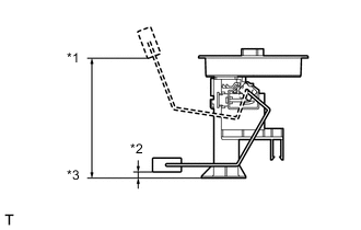
Text in Illustration *1 Float position F (upper end) *2 Float position E (lower end) *3 Fuel tank seat face Measure the dimensions between the fuel tank seat face and the float center with the float position at F (upper end) and at E (lower end).
Dimensions Float position F (upper end) to fuel tank seat face 150.3 to 158.3 mm (5.917 to 6.232 in.) Float position E (lower end) to fuel tank seat face 0.7 to 8.7 mm (0.028 to 0.343 in.) -
Check that the float moves smoothly between F (upper) and E (lower).
-
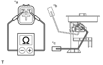
Text in Illustration *a Component without harness connected
(No. 2 Fuel Sender Gauge Assembly)
*b F (upper end) *c E (lower end) Measure the resistance according to the value(s) in the table below.
Standard Resistance Tester Connection Condition Specified Condition 1 - 2 Float position is F (upper end) 5.5 to 9.5 Ω Float position is E (lower end) 236 to 244 Ω If the value is not as specified, replace the fuel sender gauge assembly.
-