SFI SYSTEM Starter Signal Circuit
DESCRIPTION
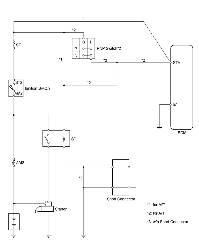
When the engine is cranked, the intake air flow becomes slow, so fuel vaporization is poor. A rich mixture is therefore necessary in order to achieve good startability. While the engine is being cranked, the battery voltage is applied to terminal STA of the ECM. The starter signal is mainly used to increase the fuel injection volume for starting and after-start injection control.
WIRING DIAGRAM
INSPECTION PROCEDURE
When using intelligent tester:
PROCEDURE
-
READ DATA LIST (STA SIGNAL)
-
Connect the intelligent tester to the DLC3.
-
Turn the ignition switch ON and turn the intelligent tester ON.
-
Enter the following menus: Powertrain / Engine and ECT / Data List / Starter Signal.
-
Check the result when the ignition switch is turned to ON and START.
Result Ignition Switch Position STA Signal Proceed to ON → START for A/T:
Display does not change for OFF → ON
A for M/T:
Display does not change for OFF → ON
B Display changes from OFF → ON C
B 
CHECK WIRE HARNESS (ECM - IGNITION SWITCH) Click here
C 
PROCEED TO NEXT CIRCUIT INSPECTION SHOWN IN PROBLEM SYMPTOMS TABLE
A 
-
-
INSPECT PARK/NEUTRAL POSITION SWITCH
-
Move the shift lever to the P or N position.
-
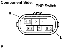
Disconnect the N8 Park/Neutral Position (PNP) switch connector.
-
Measure the resistance of the PNP switch.
Standard Tester Connection Shift Position Specified Condition 4 (B) - 5 (L) P or N Below 1 Ω 4 (B) - 5 (L) Except P or N 10 kΩ or higher
NG
REPLACE PARK/NEUTRAL POSITION SWITCH (GO TO NEXT STEP AFTER REPLACEMENT)
OK
-
-
CHECK WIRE HARNESS (ECM - IGNITION SWITCH)
-
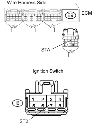
Disconnect the E9 ECM connector.
-
Disconnect the I6 ignition switch connector.
-
Measure the resistance of the wire harness side connectors.
Standard resistance Tester Connection Specified Condition E9-12 (STA) - I6-7 (ST2) Below 1 Ω E9-12 (STA) or I6-7 (ST2) - Body ground 10 kΩ or higher
NG
REPAIR OR REPLACE HARNESS AND CONNECTOR
OK
-
-
INSPECT IGNITION SWITCH
-
Inspect the ignition switch Click here.
NG
REPLACE IGNITION SWITCH (GO TO NEXT STEP AFTER REPLACEMENT)
OK
-
-
DATA LIST (STA SIGNAL)
-
Connect the intelligent tester to the DLC3.
-
Turn the ignition switch ON and turn the intelligent tester ON.
-
Enter the following menus: Powertrain / Engine and ECT / Data List / Starter Signal.
-
Check the result when the ignition switch is turned to ON and START.
OK Ignition Switch Position STA Signal ON → START Display changes from OFF → ON
NG
REPLACE ECM
OK 
END
-
When not using intelligent tester:
PROCEDURE
-
CHECK ECM (STA VOLTAGE)
-
Turn the ignition switch ON.
-
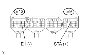
Measure the voltage of the ECM connectors.
Standard voltage Tester Connection Specified Condition E9-12 (STA) - E12-3 (E1) 0 V -
Measure the voltage of the ECM connectors when the engine is cranked.
Standard voltage Tester Connection Specified Condition E9-12 (STA) - E12-3 (E1) 6 V or more Result Result Proceed to NG for A/T A NG for M/T B OK C
B
CHECK WIRE HARNESS (ECM - IGNITION SWITCH) Click here
C
PROCEED TO NEXT CIRCUIT INSPECTION SHOWN IN PROBLEM SYMPTOMS TABLE
A
-
-
INSPECT PARK/NEUTRAL POSITION SWITCH
-
Move the shift lever to the P or N position.
-
Disconnect the N8 Park/Neutral Position (PNP) switch connector.
-
Measure the resistance of the PNP switch.
Standard Tester Connection Shift Position Specified Condition 4 (B) - 5 (L) P or N Below 1 Ω 4 (B) - 5 (L) Except P or N 10 kΩ or higher
NG
REPLACE PARK/NEUTRAL POSITION SWITCH
OK
-
-
CHECK WIRE HARNESS (ECM - IGNITION SWITCH)
-
Disconnect the E9 ECM connector.
-
Disconnect the I6 ignition switch connector.
-
Measure the resistance of the wire harness side connectors.
Standard resistance Tester Connection Specified Condition E9-12 (STA) - I6-7 (ST2) Below 1 Ω E9-12 (STA) or I6-7 (ST2) - Body ground 10 kΩ or higher
NG
REPAIR OR REPLACE HARNESS AND CONNECTOR
OK
-
-
INSPECT IGNITION SWITCH
-
Inspect the ignition switch Click here.
NG
REPLACE IGNITION SWITCH
OK
REPLACE ECM
-