FUEL INJECTOR INSTALLATION
CAUTION / NOTICE / HINT
Perform "Inspection After Repairs" after replacing the fuel injector assembly (Click here).
PROCEDURE
INSTALL FUEL INJECTOR ASSEMBLY
Tip:Perform "Inspection After Repairs" after replacing the fuel injector assembly (Click here).
-
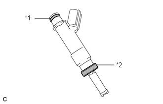
Install a new injector vibration insulator to the fuel injector.
Table 1. Text in Illustration *1
O-Ring
*2
Injector Vibration Insulator
Apply a light coat of gasoline or spindle oil to the contact surfaces of the O-ring of the fuel injector.
-
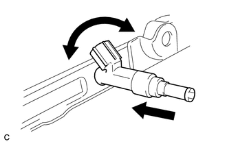
While turning the fuel injector left and right, install it to the fuel delivery pipe.
Note:Do not twist the O-ring.
After installing the fuel injectors, check that they turn smoothly. If not, replace the O-ring with a new one.
-
INSTALL FUEL DELIVERY PIPE SUB-ASSEMBLY
-
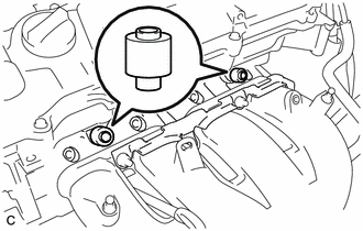
Install the 2 No. 1 delivery pipe spacers to the cylinder head.
Note:Install the No. 1 delivery pipe spacers in the correct direction.
-
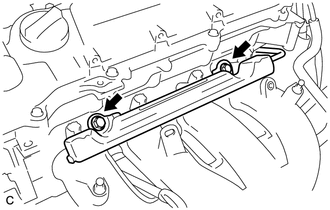
Install the fuel delivery pipe with the 4 fuel injector assemblies, and then temporarily install the 2 bolts.
Note:Do not drop the fuel injectors when installing the fuel delivery pipe.
Check that the fuel injector assemblies rotate smoothly after installing the fuel delivery pipe.
-
Tighten the 2 bolts to the specified torque.
21 N*m
214 kgf*cm
15 ft.*lbf
-
Install the bolt to secure the fuel delivery pipe.
21 N*m
214 kgf*cm
15 ft.*lbf
-
Install the wire harness bracket with the bolt.
10 N*m
102 kgf*cm
7 ft.*lbf
-
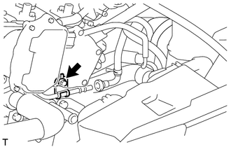
CONNECT FUEL TUBE SUB-ASSEMBLY
-
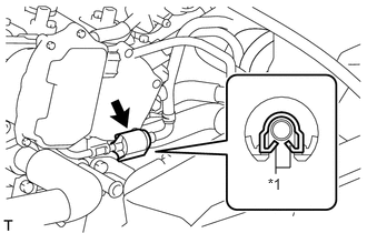
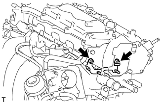
Push the fuel tube connector onto the fuel delivery pipe until a "click" sound can be heard.
Note:Check that there are no scratches or foreign matter around the contact surfaces of the fuel tube connector and pipe before performing this step.
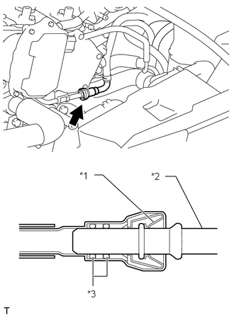
After connecting the fuel tube, check that the fuel tube connector and pipe are securely connected by pulling on them.
Table 2. Text in Illustration *1
Retainer
*2
Pipe
*3
O-Ring
-
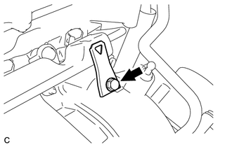
Install a new No. 2 fuel pipe clamp.
Table 3. Text in Illustration *1
Claw
-
INSTALL WIRE HARNESS CLAMP BRACKET
-
Install the wire harness clamp bracket with the 2 nuts.
18 N*m
184 kgf*cm
13 ft.*lbf
-
INSTALL AIR TUBE
CONNECT ENGINE WIRE
INSTALL BATTERY TRAY
INSTALL BATTERY
INSTALL BATTERY CLAMP SUB-ASSEMBLY
INSTALL AIR CLEANER CASE SUB-ASSEMBLY
INSTALL AIR CLEANER CAP SUB-ASSEMBLY
CONNECT CABLE TO NEGATIVE BATTERY TERMINAL
Note:When disconnecting the cable, some systems need to be initialized after the cable is reconnected (Click here).
INSPECT FOR FUEL LEAK
Make sure that there are no fuel leaks after performing maintenance on the fuel system.
Connect the intelligent tester to the DLC3.
Turn the ignition switch to ON, and push the intelligent tester main switch on.
Note:Do not start the engine.
Enter the following menus: Powertrain / Engine and ECT / Active Test / Control the Fuel Pump / Speed.
Check that there are no leaks from the fuel system.
Turn the ignition switch off.
Disconnect the intelligent tester from the DLC3.
INSTALL NO. 2 CYLINDER HEAD COVER
INSTALL RADIATOR SUPPORT OPENING COVER