FRONT WHEEL ALIGNMENT ADJUSTMENT
PROCEDURE
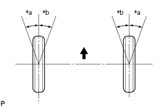
INSPECT TIRES
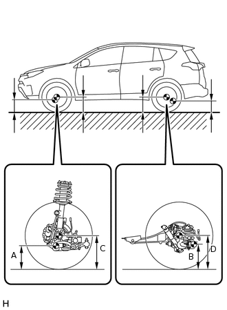
MEASURE VEHICLE HEIGHT
 Note:
Note:Before inspecting the wheel alignment, adjust the vehicle height to the specified value.
Be sure to perform the measurement on a level surface.
If it is necessary to go under the vehicle for measurement, make sure that the parking brake is applied and the vehicle is secured with chocks.
Bounce the vehicle up and down at the corners several times to stabilize the suspension.
Measure the vehicle height.
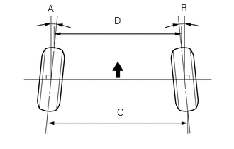
Measuring points
A
Ground clearance of center of front No. 1 lower suspension arm bushing set bolt
B
Ground clearance of center of rear No. 2 suspension arm bushing set bolt
C
Ground clearance of center of front wheel
D
Ground clearance of center of rear wheel
Note:The standard value shown here is a value that is used for adjusting the wheel alignment and does not indicate the height of an actual vehicle.
Standard Vehicle Height (Unloaded Vehicle)
Item
Front C - A
Rear D - B
-
114 mm (4.49 in.)
72 mm (2.83 in.)
Rough Road Package
104 mm (4.09 in.)
62 mm (2.44 in.)
INSPECT CAMBER, CASTER AND STEERING AXIS INCLINATION
-
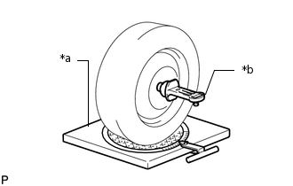
*a
Wheel Alignment Tester
*b
Camber-Caster-Kingpin Gauge
Install a camber-caster-kingpin gauge or place the front wheels on the center of a wheel alignment tester.
Inspect the camber, caster and steering axis inclination.
Standard Camber Inclination (Unloaded Vehicle)
Tire Size
Item
Camber Inclination
Right-left Difference
215/70R16
-
-0°12' +/-45' (-0.20° +/-0.75°)
30' (0.50°) or less
225/65R17
-
-0°10' +/-45' (-0.17° +/-0.75°)
30' (0.50°) or less
Rough Road Package
-0°09' +/-45' (-0.15° +/-0.75°)
30' (0.50°) or less
235/55R18
-
-0°11' +/-45' (-0.18° +/-0.75°)
30' (0.50°) or less
Rough Road Package
-0°10' +/-45' (-0.17° +/-0.75°)
30' (0.50°) or less
225/60R18
-
-0°11' +/-45' (-0.18° +/-0.75°)
30' (0.50°) or less
Standard Caster Inclination (Unloaded Vehicle)
Tire Size
Item
Caster Inclination
Right-left Difference
215/70R16
-
5°52' +/-45' (5.87° +/-0.75°)
30' (0.50°) or less
225/65R17
-
5°56' +/-45' (5.93° +/-0.75°)
30' (0.50°) or less
Rough Road Package
5°47' +/-45' (5.78° +/-0.75°)
30' (0.50°) or less
235/55R18
-
5°55' +/-45' (5.92° +/-0.75°)
30' (0.50°) or less
Rough Road Package
5°47' +/-45' (5.78° +/-0.75°)
30' (0.50°) or less
225/60R18
-
5°55' +/-45' (5.92° +/-0.75°)
30' (0.50°) or less
Standard Steering Axis Inclination (Unloaded Vehicle)
Item
Steering Axis Inclination
-
11°35' +/-30' (11.58° +/-0.50°)
Rough Road Package
11°24' +/-30' (11.40° +/-0.50°)
-
ADJUST CAMBER
Note:Inspect toe-in after the camber has been adjusted.
Remove the front wheel.
-
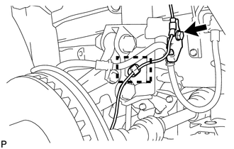
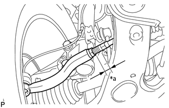
Remove the bolt, detach the clamp and disconnect the front speed sensor.
-
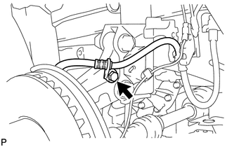
Remove the bolt and disconnect the front flexible hose.
-
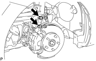
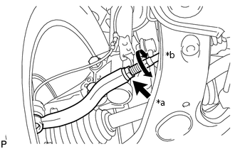
Remove the 2 nuts on the lower side of the front shock absorber.
Note:Keep the bolts inserted.
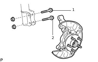
Remove the top and bottom bolts one at a time and confirm that the steering knuckle can move freely in the front shock absorber.
Note:Do not apply lubricants to the steering knuckle and shock absorber contact surfaces.
Tip:Reinstall each bolt after removing it and confirming steering knuckle movement.
If the steering knuckle does not move freely in the front shock absorber, clean the installation surfaces of the front shock absorber and the steering knuckle.
Temporarily install the 2 nuts (Step A).
-
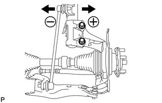
Fully push or pull the front axle hub in the direction of the required adjustment (Step B).
-
Tighten the nuts.
240 N*m
2447 kgf*cm
177 ft.*lbf
Note:Prevent the bolts from rotating when tightening the nuts.
-
Connect the front flexible hose to the steering knuckle with the bolt.
29 N*m
296 kgf*cm
21 ft.*lbf
-
Connect the front flexible hose and front speed sensor with the bolt.
29 N*m
296 kgf*cm
21 ft.*lbf
Note:Do not twist the front speed sensor when installing it.
Attach the clamp of the front speed sensor.
Install the front wheel.
Check the camber.
Standard Camber Inclination (Unloaded Vehicle)
Tire Size
Item
Camber Inclination
Right-left Difference
215/70R16
-
-0°12' +/-30' (-0.20° +/-0.50°)
30' (0.50°) or less
225/65R17
-
-0°10' +/-30' (-0.17° +/-0.50°)
30' (0.50°) or less
Rough Road Package
-0°09' +/-30' (-0.15° +/-0.50°)
30' (0.50°) or less
235/55R18
-
-0°11' +/-30' (-0.18° +/-0.50°)
30' (0.50°) or less
Rough Road Package
-0°10' +/-30' (-0.17° +/-0.50°)
30' (0.50°) or less
225/60R18
-
-0°11' +/-30' (-0.18° +/-0.50°)
30' (0.50°) or less
-
Check the camber.
If the measured value is not within the specification, calculate the required adjustment amount using the formula below.
Camber adjustment amount = center value of the specified range - measured value.
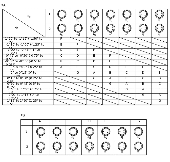
Check the combination of installed bolts. Select appropriate bolts from the table below to adjust the camber to the specified values.
Tip:Try to adjust the camber to the center of the specified range.
Move Axle toward (+) in Step (B)
Move Axle toward (-) in Step (B)
Refer to table (1) (When moving the axle toward the positive side)
Refer to table (2) (When moving the axle toward the negative side)
Note:Replace the nut with a new one when replacing a bolt.
Table (1) (To move the axle hub toward the positive side)
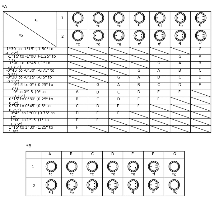
*A
Table (1) (To move the axle hub toward the positive side)
*B
Selected Bolt Combination
*a
Installed Bolt
*b
Adjusting Value
*c
Standard Bolt
*d
90105-17009
*e
90105-17010
*f
90105-17011
Table (2) (To move the axle hub toward the negative side)
*A
Table (2) (To move the axle hub toward the negative side)
*B
Selected Bolt Combination
*a
Installed Bolt
*b
Adjusting Value
*c
Standard Bolt
*d
90105-17009
*e
90105-17010
*f
90105-17011
If the camber was out of adjustment in the previous step, perform the adjust camber steps mentioned above. In step A, replace the existing bolts with the selected bolts.
Tip:Replace one bolt at a time when replacing both bolts.
INSPECT TOE-IN
-

Front of the Vehicle
Bounce the vehicle up and down at the corners to stabilize the suspension and inspect toe-in.
Toe-in (Unloaded Vehicle)
Tire Size
Item
A + B
C - D
215/70R16
-
A + B: 0°7' +/-10' (0.12°+/-0.16°)
C - D: 1.4 +/-2.0 mm (0.06 +/-0.08 in.)
225/65R17
-
A + B: 0°8' +/-10' (0.13°+/-0.16°)
C - D: 1.5 +/-2.0 mm (0.06 +/-0.08 in.)
Rough Road Package
A + B: 0°8' +/-10' (0.14°+/-0.16°)
C - D: 1.6 +/-2.0 mm (0.06 +/-0.08 in.)
235/55R18
-
A + B: 0°8' +/-10' (0.13°+/-0.16°)
C - D: 1.5 +/-2.0 mm (0.06 +/-0.08 in.)
Rough Road Package
A + B: 0°8' +/-10' (0.14°+/-0.16°)
C - D: 1.6 +/-2.0 mm (0.06 +/-0.08 in.)
225/60R18
-
A + B: 0°8' +/-10' (0.13°+/-0.16°)
C - D: 1.6 +/-2.0 mm (0.06 +/-0.08 in.)
Tip:If the toe-in is not within the specified range, adjust it at the rack ends.
-
ADJUST TOE-IN
-
*a
Difference
Make sure that the lengths of the right and left rack ends are almost the same.
Standard difference
1.5 mm (0.06 in.) or less
Remove the boot clips.
-
*a
Loosen
*b
Turn
Loosen the tie rod end lock nuts.
Turn the right and left rack ends by an equal amount to adjust the toe-in to the center value.
Tighten the tie rod end lock nuts.
88 N*m
897 kgf*cm
65 ft.*lbf
Place the boots on the seats and install the clips.
Note:Make sure that the claws of the clip are facing in the direction that the vehicle travels.
Tip:Make sure that the boots are not twisted.
-
INSPECT WHEEL ANGLE
*a
Inside
*b
Outside
Front of the Vehicle
Turn the steering wheel to the left and right full lock positions and measure the turning angle.
Standard Wheel Turning Angle (Unloaded Vehicle)
Tire Size
Item
Inside Wheel
Outside Wheel (Reference)
215/70R16
-
38°36' (36°36' to 40°36')
(38.60° (36.60° to 40.60°))
32°10' (32.17°)
225/65R17
-
38°38' (36°38' to 40°38')
(38.63° (36.63° to 40.63°))
32°04' (32.07°)
Rough Road Package
38°48' (36°48' to 40°48')
(38.80° (36.80° to 40.80°))
32°17' (32.28°)
235/55R18
-
35°46' (33°46' to 37°46')
(35.77° (33.77° to 37.77°))
30°20' (30.33°)
Rough Road Package
35°54' (33°54' to 37°54')
(35.90° (33.90° to 37.90°))
30°34' (30.57°)
225/60R18
-
35°48' (33°48' to 37°48')
(35.80° (33.80° to 37.80°))
30°24' (30.40°)
If the angles are not as specified, check and adjust the right and left rack end lengths.
PLACE FRONT WHEELS FACING STRAIGHT AHEAD
PERFORM YAW RATE SENSOR ZERO POINT CALIBRATION