SFI SYSTEM, Diagnostic DTC:P2685
| DTC Code | DTC Name |
|---|---|
| P2685 | Actuator Supply Voltage "C" Circuit Low |
DESCRIPTION
DTC No. |
Detection Item |
DTC Detection Condition |
Trouble Area |
MIL |
Memory |
|---|---|---|---|---|---|
P2685 |
Actuator Supply Voltage "C" Circuit Low |
Abnormal power supply 3 voltage. |
|
Comes on |
DTC stored |
WIRING DIAGRAM
Refer to DTC P0121 for throttle body with motor assembly circuit.
Refer to DTC P0222 for the accelerator pedal sensor assembly circuit.
CAUTION / NOTICE / HINT
If the throttle body with motor assembly is repaired or replaced, perform BPM Learning Reset.
If the Accelerator pedal sensor assembly is replaced, perform Accel Pedal Learning Value Reset.
PROCEDURE
CHECK ANY OTHER DTCS OUTPUT (IN ADDITION TO DTC P2685)
Connect the GTS to the DLC3.
Turn the ignition switch to ON.
Turn the GTS on.
Enter the following menus: Powertrain / Engine / Trouble Codes.
Check for DTCs.
Powertrain > Engine > Trouble Codes
Result
Result
Proceed to
DTC P2685 is output
A
DTC P2685 and other DTCs are output
B
Tip:If DTC P2685 and P0562 or P0563 are output simultaneously, troubleshoot for DTC P0562 or P0563 first.
READ VALUE USING GTS (SYSTEM SUPPLY VOLTAGE (CMM))
Connect the GTS to the DLC3.
Turn the ignition switch to ON.
Turn the GTS on.
Enter the following menus: Powertrain / Engine / Data List / System Supply Voltage (CMM).
Powertrain > Engine > Data List
Tester Display
System Supply Voltage (CMM)
Read the value.
Standard
11 to 14 V
Result
Proceed to
OK
NG
READ VALUE USING GTS (5V SENSOR NO.3 SUPPLY VOLTAGE (CMM))
Connect the GTS to the DLC3.
Turn the ignition switch to ON.
Turn the GTS on.
Enter the following menus: Powertrain / Engine / Data List / 5V Sensor No.3 Supply Voltage (CMM).
Powertrain > Engine > Data List
Tester Display
5V Sensor No.3 Supply Voltage (CMM)
Read the value.
OK
4750 to 5250 mV
Result
Proceed to
OK
NG
CHECK TERMINAL VOLTAGE (POWER SOURCE OF THROTTLE POSITION SENSOR)
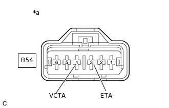
*a
Front view of wire harness connector
(to Throttle Body with Motor Assembly)
Disconnect the throttle body with motor assembly connector.
Turn the ignition switch to ON.
Measure the voltage according to the value(s) in the table below.
Standard Voltage
Tester Connection
Condition
Specified Condition
B54-4 (VCTA) - B54-3 (ETA)
Ignition switch ON
4.5 to 5.5 V
Result
Proceed to
OK
NG
NG CHECK HARNESS AND CONNECTOR (THROTTLE POSITION SENSOR - ECM)Click here
CHECK TERMINAL VOLTAGE (POWER SOURCE OF ACCELERATOR PEDAL POSITION SENSOR)
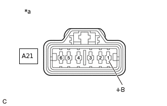
*a
Front view of wire harness connector
(to Accelerator Pedal Sensor Assembly)
Disconnect the accelerator pedal sensor assembly connector.
Turn the ignition switch to ON.
Measure the voltage according to the value(s) in the table below.
Standard Voltage
Tester Connection
Condition
Specified Condition
A21-1 (+B) - Body ground
Ignition switch ON
4.75 to 5.25 V
Result
Proceed to
OK
NG
CHECK HARNESS AND CONNECTOR (ACCELERATOR PEDAL SENSOR ASSEMBLY - ECM)
Disconnect the ECM connector.
Disconnect the accelerator pedal sensor assembly connector.
Measure the resistance according to the value(s) in the table below.
Standard Resistance
Tester Connection
Condition
Specified Condition
A21-1 (+B) - A35-46 (+B)
Always
Below 1 Ω
A21-2 (S2) - A35-34 (S2)
Always
Below 1 Ω
A21-3 (M2-) - A35-44 (M2-)
Always
Below 1 Ω
A21-4 (KD) - A35-36 (KD)
Always
Below 1 Ω
A21-5 (M1-) - A35-47 (M1-)
Always
Below 1 Ω
A21-6 (S1) - A35-35 (S1)
Always
Below 1 Ω
A21-1 (+B) or A35-46 (+B) - Body ground and other terminals
Always
10 kΩ or higher
A21-2 (S2) or A35-34 (S2) - Body ground and other terminals
Always
10 kΩ or higher
A21-3 (M2-) or A35-44 (M2-) - Body ground and other terminals
Always
10 kΩ or higher
A21-4 (KD) or A35-36 (KD) - Body ground and other terminals
Always
10 kΩ or higher
A21-5 (M1-) or A35-47 (M1-) - Body ground and other terminals
Always
10 kΩ or higher
A21-6 (S1) or A35-35 (S1) - Body ground and other terminals
Always
10 kΩ or higher
Result
Proceed to
OK
NG
NG REPAIR OR REPLACE HARNESS OR CONNECTOR
REPLACE ACCELERATOR PEDAL SENSOR ASSEMBLY
Replace the accelerator pedal sensor assembly.
Result
Proceed to
NEXT
CHECK WHETHER DTC OUTPUT RECURS (DTC P2685)
Connect the GTS to the DLC3.
Turn the ignition switch to ON.
Turn the GTS on.
Clear the DTCs.
Powertrain > Engine > Clear DTCs
Turn the ignition switch off and wait for a few minutes.
Perform the drive test.
Turn the GTS on.
Enter the following menus: Powertrain / Engine / Trouble Codes.
Check for DTCs.
Powertrain > Engine > Trouble Codes
Result
Result
Proceed to
DTC P2685 is output
A
DTCs are not output
B
B END
CHECK HARNESS AND CONNECTOR (THROTTLE POSITION SENSOR - ECM)
Disconnect the throttle body with motor assembly connector.
Disconnect the ECM connector.
Measure the resistance according to the value(s) in the table below.
Standard Resistance
Tester Connection
Condition
Specified Condition
B54-4 (VCTA) - B55-34 (VCTA)
Always
Below 1 Ω
B54-5 (VTA) - B55-10 (VTA)
Always
Below 1 Ω
B54-6 (VTA2) - B55-11 (VTA2)
Always
Below 1 Ω
B54-3 (ETA) - B55-22 (ETA)
Always
Below 1 Ω
B54-4 (VCTA) or B55-34 (VCTA) - Body ground and other terminals
Always
10 kΩ or higher
B54-5 (VTA) or B55-10 (VTA) - Body ground and other terminals
Always
10 kΩ or higher
B54-6 (VTA2) or B55-11 (VTA2) - Body ground and other terminals
Always
10 kΩ or higher
B54-3 (ETA) or B55-22 (ETA) - Body ground and other terminals
Always
10 kΩ or higher
Result
Proceed to
OK
NG
NG REPAIR OR REPLACE HARNESS OR CONNECTOR
REPLACE THROTTLE BODY WITH MOTOR ASSEMBLY
Replace the throttle body with motor assembly.
Result
Proceed to
NEXT
NEXT CHECK WHETHER DTC OUTPUT RECURS (DTC P2685)Click here