POWER MIRROR CONTROL SYSTEM(w/ Memory) Power Retractable Mirrors do not Operate with Power Retract Mirror Switch
DESCRIPTION
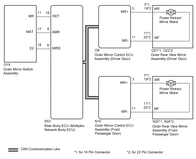
The outer mirror switch assembly sends the retractable outer mirror switch signal to the main body ECU (multiplex network body ECU). The main body ECU (multiplex network body ECU) then sends the mirror retract/return signal to each outer mirror control ECU assembly via CAN communication. Based on the signal, each outer mirror control ECU assembly retracts or returns its corresponding outer rear view mirror assembly.
WIRING DIAGRAM
CAUTION / NOTICE / HINT
Note
-
The power mirror control system (w/ Memory) uses the CAN communication system. Inspect the communication function by following How to Proceed with Troubleshooting. Troubleshoot the power mirror control system (w/ Memory) after confirming that the communication systems are functioning properly.
-
Before replacing the main body ECU (multiplex network body ECU), refer to Service Bulletin.
PROCEDURE
-
READ VALUE USING GTS
-
Connect the GTS to the DLC3.
-
Turn the engine switch on (IG).
-
Turn the GTS on.
-
Enter the following menus: Body Electrical / Main Body / Data List.
-
Read the Data List according to the display on the GTS.
Body Electrical > Main Body > Data ListTester Display Measurement Item Range Normal Condition Diagnostic Note Outer Mirror Fold SW Retractable outer mirror switch signal OFF or ON OFF: Retractable outer mirror switch not in retract position
ON: Retractable outer mirror switch in retract position
-
Body Electrical > Main Body > Data ListTester Display Outer Mirror Fold SW OK On the GTS screen, ON or OFF is displayed accordingly. Result Proceed to OK NG
NG 
INSPECT OUTER MIRROR SWITCH ASSEMBLY Click here
OK 
-
-
PERFORM ACTIVE TEST USING GTS
-
Enter the following menus: Body Electrical / Mirror L or Mirror R / Active Test.
-
Perform the Active Test according to the display on the GTS.
Body Electrical > Mirror L > Active TestTester Display Measurement Item Control Range Diagnostic Note Mirror Fold/Return Mirror retract operation OFF, Return or Fold
-
Operate with the engine switch on (IG) and the vehicle stopped.
-
This test activates the Fold / Return.
-
This operation can be confirmed by watching the mirror move in the desired direction.
Body Electrical > Mirror L > Active TestTester Display Mirror Fold/Return
Body Electrical > Mirror R > Active TestTester Display Measurement Item Control Range Diagnostic Note Mirror Fold/Return Mirror retract operation OFF, Return or Fold
-
Operate with the engine switch on (IG) and the vehicle stopped.
-
This test activates the Fold / Return.
-
This operation can be confirmed by watching the mirror move in the desired direction.
Body Electrical > Mirror R > Active TestTester Display Mirror Fold/Return Result Result Proceed to Outer rear view mirror assemblies operate normally A Outer rear view mirror assembly (driver door) does not operate normally B Outer rear view mirror assembly (front passenger door) does not operate normally C -
A 
REPLACE MAIN BODY ECU (MULTIPLEX NETWORK BODY ECU) Click here
C
CHECK HARNESS AND CONNECTOR (OUTER MIRROR CONTROL ECU ASSEMBLY (FRONT PASSENGER DOOR) - OUTER REAR VIEW MIRROR ASSEMBLY (FRONT PASSENGER DOOR)) Click here
B
-
-
CHECK HARNESS AND CONNECTOR (OUTER MIRROR CONTROL ECU ASSEMBLY (DRIVER DOOR) - OUTER REAR VIEW MIRROR ASSEMBLY (DRIVER DOOR))
-
Disconnect the O9 outer mirror control ECU assembly (driver door) connector.
-
Disconnect the O21*1 or O22*2 outer rear view mirror assembly (driver door) connector.
-
*1: for 16 Pin Connector
-
*2: for 22 Pin Connector
-
-
Measure the resistance according to the value(s) in the table below.
Standard Resistance for 16 Pin Connector: Tester Connection Condition Specified Condition O9-3 (MR+) - O21-3 (MR) Always Below 1 Ω O9-11 (MR-) - O21-11 (MF) Always Below 1 Ω O9-3 (MR+) or O21-3 (MR) - Body ground Always 10 kΩ or higher O9-11 (MR-) or O21-11 (MF) - Body ground Always 10 kΩ or higher for 22 Pin Connector: Tester Connection Condition Specified Condition O9-3 (MR+) - O22-19 (MR) Always Below 1 Ω O9-11 (MR-) - O22-20 (MF) Always Below 1 Ω O9-3 (MR+) or O22-19 (MR) - Body ground Always 10 kΩ or higher O9-11 (MR-) or O22-20 (MF) - Body ground Always 10 kΩ or higher Result Proceed to OK NG
NG
REPAIR OR REPLACE HARNESS OR CONNECTOR
OK
-
-
INSPECT OUTER REAR VIEW MIRROR ASSEMBLY (DRIVER DOOR) (RETRACTABLE MIRROR)
-
Remove the outer rear view mirror assembly (driver door).
-
Inspect the outer rear view mirror assembly (driver door)(retractable mirror).
Result Proceed to OK NG
NG
REPLACE OUTER REAR VIEW MIRROR ASSEMBLY (DRIVER DOOR) Click here
OK
-
-
REPLACE OUTER MIRROR CONTROL ECU ASSEMBLY (DRIVER DOOR)
-
Temporarily replace the outer mirror control ECU assembly (driver door) with a new or known good one.
Result Proceed to NEXT
NEXT
-
-
CHECK POWER RETRACT MIRROR FUNCTION
-
Check the power retract mirror function operates normally.
OK Power retract mirror function operates normally. Result Proceed to OK NG
OK
END (OUTER MIRROR CONTROL ECU ASSEMBLY (DRIVER DOOR) WAS DEFECTIVE)
NG
REPLACE MAIN BODY ECU (MULTIPLEX NETWORK BODY ECU) Click here
-
-
CHECK HARNESS AND CONNECTOR (OUTER MIRROR CONTROL ECU ASSEMBLY (FRONT PASSENGER DOOR) - OUTER REAR VIEW MIRROR ASSEMBLY (FRONT PASSENGER DOOR))
-
Disconnect the N10 outer mirror control ECU assembly (front passenger door) connector.
-
Disconnect the N23*1 or N24*2 outer rear view mirror assembly (front passenger door) connector.
-
*1: for 16 Pin Connector
-
*2: for 22 Pin Connector
-
-
Measure the resistance according to the value(s) in the table below.
Standard Resistance for 16 Pin Connector: Tester Connection Condition Specified Condition N10-3 (MR+) - N23-3 (MR) Always Below 1 Ω N10-11 (MR-) - N23-11 (MF) Always Below 1 Ω N10-3 (MR+) or N23-3 (MR) - Body ground Always 10 kΩ or higher N10-11 (MR-) or N23-11 (MF) - Body ground Always 10 kΩ or higher for 22 Pin Connector: Tester Connection Condition Specified Condition N10-3 (MR+) - N24-19 (MR) Always Below 1 Ω N10-11 (MR-) - N24-20 (MF) Always Below 1 Ω N10-3 (MR+) or N24-19 (MR) - Body ground Always 10 kΩ or higher N10-11 (MR-) or N24-20 (MF) - Body ground Always 10 kΩ or higher Result Proceed to OK NG
NG
REPAIR OR REPLACE HARNESS OR CONNECTOR
OK
-
-
INSPECT OUTER REAR VIEW MIRROR ASSEMBLY (FRONT PASSENGER DOOR) (RETRACTABLE MIRROR)
-
Remove the outer rear view mirror assembly (front passenger door).
-
Inspect the outer rear view mirror assembly (front passenger door)(retractable mirror).
Result Proceed to OK NG
NG
REPLACE OUTER REAR VIEW MIRROR ASSEMBLY (FRONT PASSENGER DOOR) Click here
OK
-
-
REPLACE OUTER MIRROR CONTROL ECU ASSEMBLY (FRONT PASSENGER DOOR)
-
Temporarily replace the outer mirror control ECU assembly (front passenger door) with a new or known good one.
Result Proceed to NEXT
NEXT
-
-
CHECK POWER RETRACT MIRROR FUNCTION
-
Check the power retract mirror function operates normally.
OK Power retract mirror function operates normally. Result Proceed to OK NG
OK
END (OUTER MIRROR CONTROL ECU ASSEMBLY (FRONT PASSENGER DOOR) WAS DEFECTIVE)
NG
REPLACE MAIN BODY ECU (MULTIPLEX NETWORK BODY ECU) Click here
-
-
INSPECT OUTER MIRROR SWITCH ASSEMBLY
-
Remove the outer mirror switch assembly.
-
Inspect the outer mirror switch assembly.
Result Proceed to OK NG
NG
REPLACE OUTER MIRROR SWITCH ASSEMBLY Click here
OK
-
-
CHECK HARNESS AND CONNECTOR (OUTER MIRROR SWITCH ASSEMBLY - MAIN BODY ECU (MULTIPLEX NETWORK BODY ECU))
-
Disconnect the O19 outer mirror switch assembly.
-
Disconnect the K53 main body ECU (multiplex network body ECU).
-
Measure the resistance according to the value(s) in the table below.
Standard Resistance Tester Connection Condition Specified Condition O19-11 (MR) - K53-16 (RET) Always Below 1 Ω O19-11 (MR) or K53-16 (RET) - Body ground Always 10 kΩ or higher O19-17 (MAT) - K53-6 (AMR) Always Below 1 Ω O19-17 (MAT) or K53-6 (AMR) - Body ground Always 10 kΩ or higher O19-18 (E2) - K53-9 (MIRE) Always Below 1 Ω O19-18 (E2) or K53-9 (MIRE) - Body ground Always 10 kΩ or higher Result Proceed to OK NG
OK
REPLACE MAIN BODY ECU (MULTIPLEX NETWORK BODY ECU) Click here
NG
REPAIR OR REPLACE HARNESS OR CONNECTOR
-