AUTOMATIC HIGH BEAM SYSTEM TERMINALS OF ECU
CHECK AFS ECU (HEADLIGHT SWIVEL ECU ASSEMBLY)

Disconnect the A93 AFS ECU (headlight swivel ECU assembly) connector.
Measure the resistance according to the value(s) in the table below.
Terminal No. (Symbol)
Wiring Color
Terminal Description
Condition
Specified Condition
A93-22 (E1) - Body ground
W-B - Body ground
AFS ECU (headlight swivel ECU assembly) ground
Always
Below 1 Ω
If the result is not as specified, there may be a malfunction in the wire harness.
Measure the voltage according to the value(s) in the table below.
Terminal No. (Symbol)
Wiring Color
Terminal Description
Condition
Specified Condition
A93-15 (IG) - Body ground
L - Body ground
AFS ECU (headlight swivel ECU assembly) power supply
Ignition switch off
Below 1 V
Ignition switch ON
11 to 14 V
If the result is not as specified, there may be a malfunction in the wire harness.
Reconnect the A93 AFS ECU (headlight swivel ECU assembly) connector.
Measure the voltage and check for pulses according to the value(s) in the table below.
Terminal No. (Symbol)
Wiring Color
Terminal Description
Condition
Specified Condition
A93-30 (LHT) - A93-22 (E1)
LG - W-B
LIN communication
Ignition switch off
Below 1 V
Ignition switch ON
Pulse generation
A93-12 (CANH) - A93-22 (E1)
Y - W-B
CAN communication
Ignition switch off
Below 1 V
Ignition switch ON
Pulse generation
A93-13 (CANL) - A93-22 (E1)
W - W-B
CAN communication
Ignition switch off
Below 1 V
Ignition switch ON
Pulse generation
If the result is not as specified, the AFS ECU (headlight swivel ECU assembly) may be malfunctioning.
CHECK INSTRUMENT PANEL JUNCTION BLOCK ASSEMBLY AND MAIN BODY ECU (MULTIPLEX NETWORK BODY ECU)
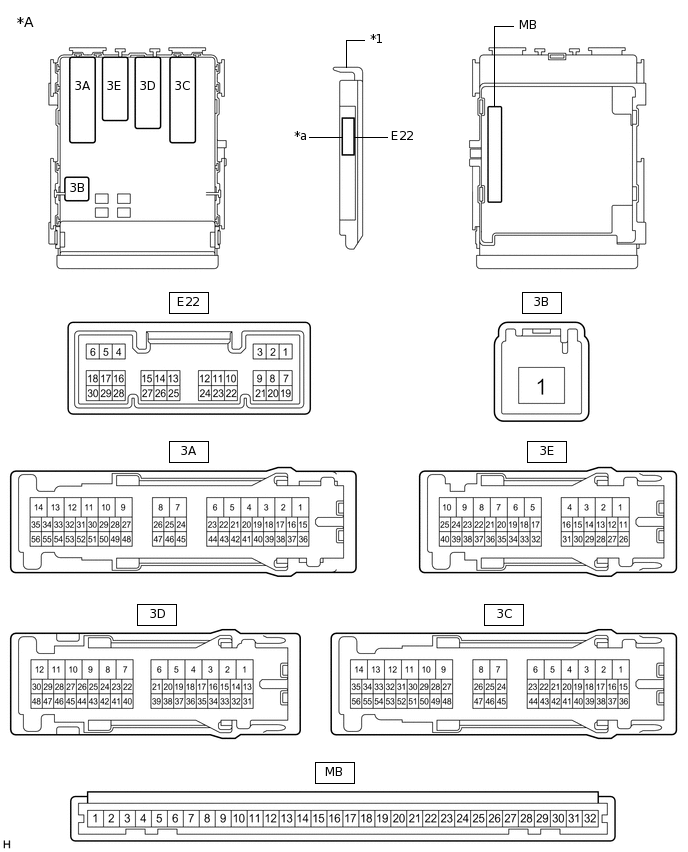
*A
Main Body ECU (Multiplex Network Body ECU) with 1 Connector
-
-
*1
Main Body ECU (Multiplex Network Body ECU)
-
-
*a
1 Connector
-
-
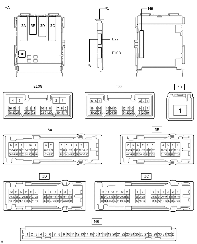
*A
Main Body ECU (Multiplex Network Body ECU) with 2 Connectors
-
-
*1
Main Body ECU (Multiplex Network Body ECU)
-
-
*a
2 Connectors
-
-
Measure the voltage and check for pulses according to the value(s) in the table below.
Terminal No. (Symbol)
Wiring Color
Terminal Description
Condition
Specified Condition
3A-54 - Body ground
LG - Body ground
High beam headlight drive output
Dimmer switch in high or high flash position
Below 1 V
Dimmer switch in low position
11 to 14 V
E22-5 (HU) - Body ground
P - Body ground
Dimmer switch high position signal input
Dimmer switch in high position
Below 1 V
Dimmer switch not in high position
11 to 14 V
E22-20 (CLTB) - E22-22 (CLTE)
W - V
Automatic light control sensor power supply output
Ignition switch off
Below 1 V
Ignition switch ON, light control switch in AUTO position
11 to 14 V
E22-21 (CLTS) - Body ground
Y - Body ground
Automatic light control sensor signal input
Ignition switch off
Below 1 V
Automatic light control system operating
Pulse generation
(See waveform 1)
E22-28 (A) - Body ground
V - Body ground
Light control switch AUTO position signal input
Light control switch in AUTO position
Below 1 V
Light control switch not in AUTO position
Pulse generation
E22-14 (CANH) - Body ground
G - Body ground
CAN Communication
Ignition switch off
Below 1 V
Ignition switch ON
Pulse generation
E22-13 (CANL) - Body ground
W - Body ground
CAN Communication
Ignition switch off
Below 1 V
Ignition switch ON
Pulse generation
If the result is not as specified, the main body ECU (multiplex network body ECU) or instrument panel junction block assembly may be malfunctioning.
-
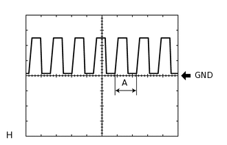
Waveform 1
Item
Content
Tool setting
5 V/DIV., 5 ms./DIV.
Tip:If the ambient light becomes brighter, width A becomes narrower.
-
CHECK INNER REAR VIEW MIRROR ASSEMBLY

Disconnect the O3 inner rear view mirror assembly connector.
Measure the resistance according to the value(s) in the table below.
Terminal No. (Symbol)
Wiring Color
Terminal Description
Condition
Specified Condition
O3-1 (E) - Body ground
W-B - Body ground
Inner rear view mirror assembly ground
Always
Below 1 Ω
If the result is not as specified, there may be a malfunction in the wire harness.
Measure the voltage according to the value(s) in the table below.
Terminal No. (Symbol)
Wiring Color
Terminal Description
Condition
Specified Condition
O3-4 (IG) - Body ground
L - Body ground
Inner rear view mirror assembly power supply
Ignition switch off
Below 1 V
Ignition switch ON
11 to 14 V
If the result is not as specified, there may be a malfunction in the wire harness.
Reconnect the O3 inner rear view mirror assembly connector.
Measure the voltage or check for pulses according to the value(s) in the table below.
Terminal No. (Symbol)
Wiring Color
Terminal Description
Condition
Specified Condition
O3-5 (LIN) - O3-1 (E)
LG - W-B
LIN communication
Ignition switch off
Below 1 V
Automatic high beam system operating
Pulse generation
(See waveform 1)
If the result is not as specified, the inner rear view mirror assembly may be malfunctioning.
-
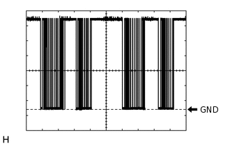
Waveform 1
Item
Content
Tool setting
2 V/DIV., 10 ms./DIV.
-