TRANSFER ASSEMBLY REASSEMBLY
-
INSTALL TRANSFER DRIVE SPROCKET SUB-ASSEMBLY (for A.D.D. Manual Shift Type)
-
Apply gear oil to the connecting areas of the clutch sleeve and drive sprocket.
-
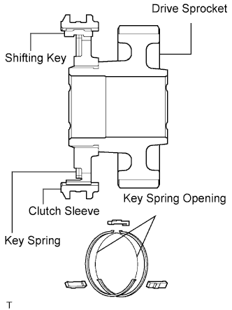
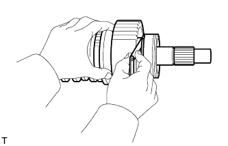
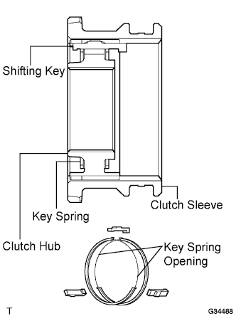
Install the clutch sleeve and 3 shifting keys to the drive sprocket with the 2 shifting key springs.
Note
-
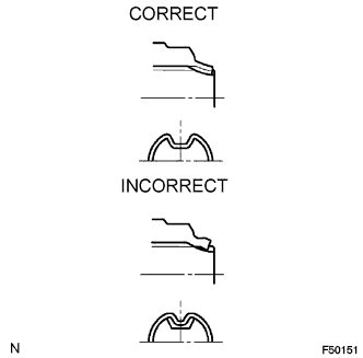
Make sure to install the clutch sleeve in the correct direction.
-
Set the key springs so that their openings do not overlap, as shown in the illustration.
-
Make sure that the key springs are firmly connected to the shifting keys.
-
Make sure that the clutch sleeve and drive sprocket move smoothly.
-
-
Apply gear oil to the front drive synchronizer ring's taper cone side.
-
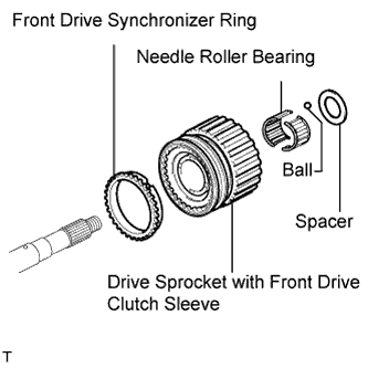
Install the front drive synchronizer ring.
-
Apply gear oil to the output shaft and needle roller bearing.
-
Install the needle roller bearing in the drive sprocket.
-
Install the drive sprocket (with clutch sleeve).
-
Install the ball. Install the spacer so that it is aligned with the ball.
-
-
INSTALL TRANSFER DRIVE SPROCKET SUB-ASSEMBLY (for Normal Shift Type)
-
Apply gear oil to the connecting areas of the clutch sleeve and drive sprocket.
-
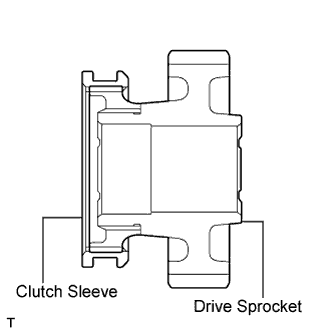
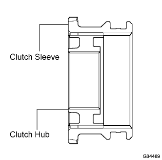
Install the clutch sleeve to the drive sprocket.
Note
-
Make sure to install the clutch sleeve in the correct direction.
-
Make sure that the clutch sleeve and drive sprocket move smoothly.
-
-
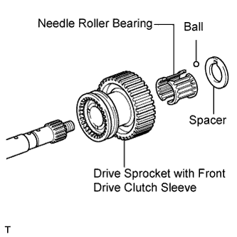
Apply gear oil to the output shaft and needle roller bearing.
-
Install the needle roller bearing in the drive sprocket.
-
Install the drive sprocket (with clutch sleeve).
-
Install the ball. Install the spacer so that it is aligned with the ball.
-
-
INSTALL REAR TRANSFER OUTPUT SHAFT RADIAL BALL BEARING
-
Apply gear oil to the connecting areas of the output shaft and bearing.
-
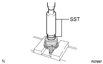
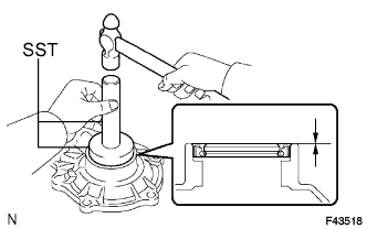
Using SST and a press, press in a new bearing with the outer race snap ring groove toward the rear.
- SST
- 09316-60011 ( 09316-00011, 09316-00071 )
-
-
CHECK TRANSFER DRIVE SPROCKET THRUST CLEARANCE
-
Using a feeler gauge, measure the thrust clearance.
Standard thrust clearance 0.10 to 0.25 mm (0.0039 to 0.0098 in.) Maximum thrust clearance 0.25 mm (0.0098 in.) If the thrust clearance is greater than the maximum, replace the drive sprocket.
-
-
INSTALL TRANSFER HIGH & LOW CLUTCH SLEEVE (for Manual Transmission)
-
Apply gear oil to the connecting areas of the clutch sleeve and clutch hub.
-
Install the clutch sleeve and 3 shifting keys to the clutch hub with the 2 shifting key springs.
Note
-
Make sure to install the clutch sleeve in the correct direction.
-
Set the key springs so that their openings do not overlap, as shown in the illustration.
-
Make sure that the key springs are firmly connected to the shifting key.
-
Make sure that the clutch sleeve and clutch hub move smoothly.
-
-
-
INSTALL TRANSFER HIGH & LOW CLUTCH SLEEVE (for Automatic Transmission)
-
Apply gear oil to the connecting areas of the clutch sleeve and clutch hub.
-
Install the clutch to the clutch hub.
Note
-
Make sure to install the clutch sleeve in the correct direction.
-
Make sure that the clutch sleeve and clutch hub move smoothly.
-
-
-
INSTALL TRANSFER CLUTCH HUB
-
M/T:
Apply gear oil to the connecting areas of a new key retainer and the output shaft.
-
M/T:
Using SST and a hammer, tap in the key retainer.
- SST
- 09316-60011 ( 09316-00011 )
Note
Be careful not to deform or damage the key retainer.
-
Apply gear oil to the connecting areas of the clutch hub and output shaft.
-
Using a press, press in the clutch hub.
-
-
INSTALL TRANSFER OUTPUT SHAFT SHAFT SNAP RING
-
Select a new snap ring that allows the minimum axial free play.
Standard snap ring thickness Mark Specified Condition K 2.00 to 2.05 mm (0.0787 to 0.0807 in.) L 2.05 to 2.10 mm (0.0807 to 0.0827 in.) A 2.10 to 2.15 mm (0.0827 to 0.0846 in.) B 2.15 to 2.20 mm (0.0846 to 0.0866 in.) C 2.20 to 2.25 mm (0.0866 to 0.0886 in.) D 2.25 to 2.30 mm (0.0886 to 0.0906 in.) E 2.30 to 2.35 mm (0.0906 to 0.0925 in.) F 2.35 to 2.40 mm (0.0925 to 0.0945 in.) G 2.40 to 2.45 mm (0.0945 to 0.0965 in.) H 2.45 to 2.50 mm (0.0965 to 0.0984 in.) J 2.50 to 2.55 mm (0.0984 to 0.1004 in.) -
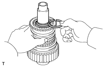
Using a snap ring expander, install the snap ring.
Note
Make sure that the snap ring is firmly installed to the groove.
-
-
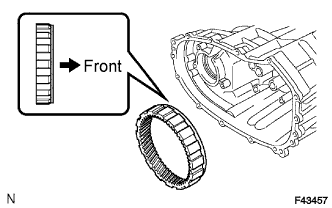
INSTALL TRANSFER LOW PLANETARY RING GEAR
-
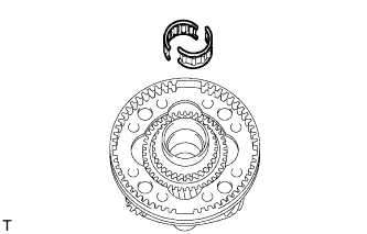
Install the ring gear to the case front.
Note
Make sure to install the ring gear in the correct direction.
-
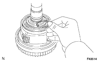
Using a screwdriver, install the snap ring.
Note
Make sure that the snap ring is firmly installed to the groove.
-
-
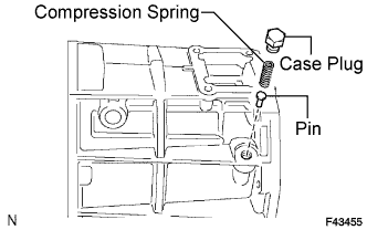
INSTALL PIN
-
INSTALL COMPRESSION SPRING
-
INSTALL TRANSFER CASE PLUG
-
Apply adhesive to the threads of the plug.
Adhesive Toyota Genuine Adhesive 1344, Three Bond 1344 or equivalent -
Install the plug.
- Torque:
- 18.6 N*m { 190 kgf*cm, 14 ft.*lbf }
-
-
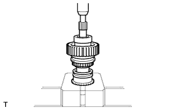
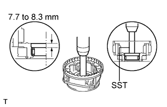
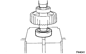
INSTALL TRANSFER LOW PLANETARY GEAR BEARING
-
Using SST and a press, press in a new bearing.
- SST
- 09950-60010 ( 09951-00570 )
- 09950-70010 ( 09951-00710 )
Bearing depth 7.7 to 8.3 mm (0.303 to 0.327 in.)
-
-
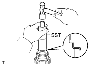
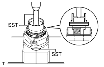
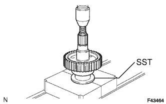
INSTALL TRANSFER INPUT SHAFT BEARING
-
Using SST and a press, press in a new bearing with the groove facing forward.
- SST
- 09223-15020
- 09515-30010
- 09950-70010 ( 09951-07100 )
-
-
INSTALL TRANSFER INPUT BEARING SHAFT SNAP RING
-
Select a new snap ring that allows 0.1 mm (0.004 in.) or less of axial free play.
Standard snap ring thickness Mark Specified Condition 1 1.45 to 1.50 mm (0.0571 to 0.0591 in.) 2 1.50 to 1.55 mm (o.0591 to 0.0610 in.) 3 1.55 to 1.60 mm (0.0610 to 0.0630 in.) 4 1.60 to 1.65 mm (0.0630 to 0.0650 in.) 5 1.65 to 1.70 mm (0.0650 to 0.0669 in.) -
Using a snap ring expander, install the snap ring.
Note
Make sure that the snap ring is firmly installed to the groove.
-
-
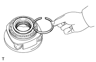
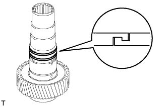
INSTALL NO. 1 TRANSFER INPUT SHAFT SEAL RING
-
Apply gear oil to the 2 seal rings.
-
Install the 2 seal rings to the input shaft.
Tech Tips
Engage the seal rings securely to eliminate clearance, as shown in the illustration.
-
-
INSTALL TRANSFER LOW PLANETARY GEAR BEARING
-
Install the bearing to the low planetary gear.
Note
Make sure to install the bearing in the correct direction.
-
-
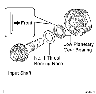
INSTALL NO. 1 TRANSFER THRUST BEARING RACE
-
Install the bearing race to the low planetary gear.
-
-
INSTALL TRANSFER INPUT SHAFT
-
Apply gear oil to the contact surfaces of the input shaft and low planetary gear.
-
Install the input shaft to the low planetary gear.
-
-
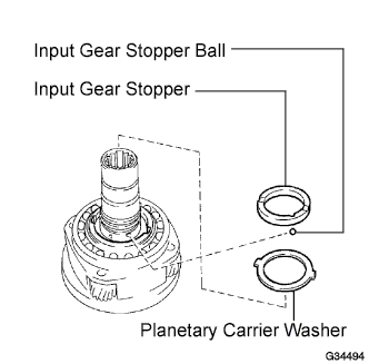
INSTALL MANUAL TRANSFER PLANETARY CARRIER WASHER
-
Apply gear oil to the washer.
-
Install the washer to the low planetary gear.
-
-
INSTALL TRANSFER INPUT GEAR STOPPER BALL
-
Install the ball to the low planetary gear.
-
-
INSTALL TRANSFER INPUT GEAR STOPPER
-
Install the stopper to the low planetary gear.
-
-
INSTALL TRANSFER INPUT GEAR STOPPER SHAFT SNAP RING
-
Select a new snap ring that allows 0.05 to 0.15 mm (0.0020 to 0.0059 in.) of axial free play.
Standard snap ring thickness Mark Specified Condition A 2.10 to 2.15 mm (0.0827 to 0.0846 in.) B 2.15 to 2.20 mm (0.0846 to 0.0866 in.) C 2.20 to 2.25 mm (0.0866 to 0.0886 in.) D 2.25 to 2.30 mm (0.0886 to 0.0906 in.) E 2.30 to 2.35 mm (0.0906 to 0.0925 in.) F 2.35 to 2.40 mm (0.0925 to 0.0945 in.) G 2.40 to 2.45 mm (0.0945 to 0.0965 in.) H 2.45 to 2.50 mm (0.0965 to 0.0984 in.) J 2.50 to 2.55 mm (0.0984 to 0.1004 in.) K 2.55 to 2.60 mm (0.1004 to 0.1024 in.) L 2.60 to 2.65 mm (0.1024 to 0.1043 in.) M 2.65 to 2.70 mm (0.1043 to 0.1063 in.) N 2.70 to 2.75 mm (0.1063 to 0.1083 in.) P 2.75 to 2.80 mm (0.1083 to 0.1102 in.) Q 2.80 to 2.85 mm (0.1102 to 0.1122 in.) R 2.85 to 2.90 mm (0.1122 to 0.1142 in.) S 2.90 to 2.95 mm (0.1142 to 0.1161 in.) T 2.95 to 3.00 mm (0.1161 to 0.1181 in.) U 3.00 to 3.05 mm (0.1181 to 0.1201 in.) -
Using a snap ring expander, install the snap ring.
Note
Make sure that the snap ring is firmly installed to the groove.
-
-
INSTALL TRANSFER CASE OIL SEAL
-
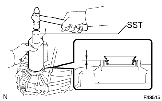
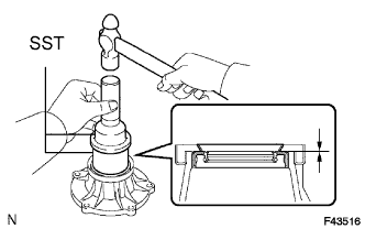
Using SST and a hammer, tap in a new oil seal until its surface is flush with the case upper surface (No. 1).
- SST
- 09316-60011
Oil seal depth -0.5 to 0.5 mm (-0.020 to 0.020 in.) Note
Be careful not to damage the case front.
-
Coat the lip of the seal with MP grease.
-
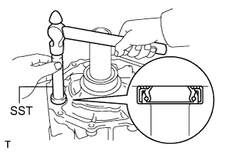
Using SST and a hammer, tap in a new oil seal until its surface is flush with the case upper surface (No. 2).
- SST
- 09316-60011
Oil seal depth -0.5 to 0.5 mm (-0.020 to 0.020 in.) Note
Be careful not to damage the case front.
-
Coat the lip of the seal with MP grease.
-
-
INSTALL FRONT TRANSFER OUTPUT SHAFT NEEDLE ROLLER BEARING
-
Apply gear oil to the bearing.
-
Install the bearing to the low planetary gear.
-
-
INSTALL TRANSFER LOW PLANETARY GEAR SPLINE PIECE
-
Install the gear spline piece to the low planetary gear.
-
Using a screwdriver, install the snap ring.
Note
Be careful not to damage the gear spline piece.
-
-
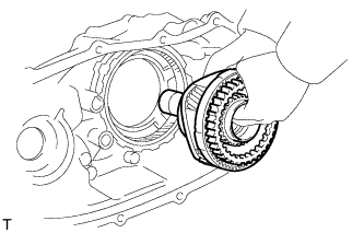
INSTALL TRANSFER LOW PLANETARY GEAR ASSEMBLY WITH TRANSFER INPUT SHAFT
-
Install the low planetary gear with input shaft.
Tech Tips
If necessary, heat the case front to about 50 to 80°C (122 to 176°F).
-
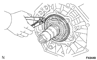
Using a snap ring expander, install the snap ring.
Note
Make sure that the snap ring is firmly installed to the groove.
-
-
INSTALL FRONT TRANSFER DRIVE CLUTCH SYNCHRONIZER RING (for Manual Transmission)
-
Apply gear oil to the synchronizer ring's tapered cone side.
-
Install the synchronizer ring to the low planetary gear.
-
-
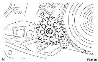
INSTALL TRANSFER OIL PUMP GEAR
-
Apply gear oil to the sliding surface of the oil pump gear.
-
Install the oil pump gear with the nut.
-
-
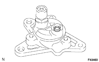
INSTALL TRANSFER OIL PUMP BODY O-RING
-
Coat a new O-ring with gear oil and install it to the pump body.
-
-
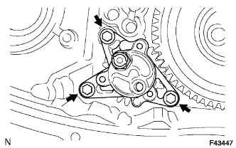
INSTALL TRANSFER OIL PUMP BODY SUB-ASSEMBLY
-
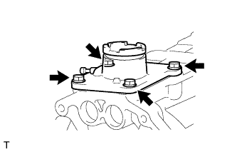
Install the oil pump body with the 3 bolts.
- Torque:
- 7.5 N*m { 76 kgf*cm, 66 in.*lbf }
-
-
INSTALL TRANSFER CASE MAGNET
-
INSTALL TRANSFER OIL SEPARATOR SUB-ASSEMBLY
-
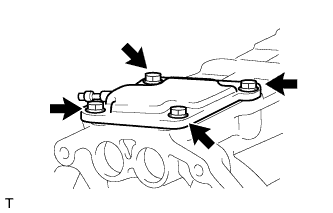
Install the oil separator with the 3 bolts.
- Torque:
- 7.5 N*m { 76 kgf*cm, 66 in.*lbf }
-
-
INSTALL NO. 1 TRANSFER CASE PLUG (for Filler)
-
Install a new gasket and the filler plug.
- Torque:
- 37 N*m { 377 kgf*cm, 27 ft.*lbf }
-
-
INSTALL NO. 1 TRANSFER CASE PLUG (for Drain)
-
Install a new gasket and the drain plug.
- Torque:
- 37 N*m { 377 kgf*cm, 27 ft.*lbf }
-
-
INSTALL TRANSFER INPUT GEAR RADIAL BALL BEARING
-
Apply gear oil to the contact surfaces of the bearing and driven sprocket.
-
Using SST and a press, press in a new bearing.
- SST
- 09316-60011 ( 09316-00031 )
Note
After press-fitting the bearing to the driven sprocket, check that the bearing moves smoothly.
-
-
INSTALL TRANSFER DRIVEN SPROCKET BEARING
-
Apply gear oil to the contact surfaces of the bearing and driven sprocket.
-
Using a press, press in a new bearing.
Note
After press-fitting the bearing to the driven sprocket, check that the bearing moves smoothly.
-
-
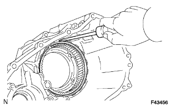
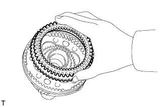
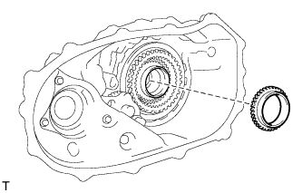
INSTALL REAR TRANSFER OUTPUT SHAFT, TRANSFER FRONT DRIVE CHAIN AND TRANSFER DRIVEN SPROCKET
-
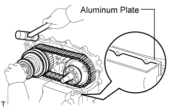
Mount the rear case in a vise.
Note
Place aluminum plates on the vise to prevent damage to the rear case.
-
Install the output shaft and driven sprocket to the front drive chain.
-
Install the output shaft, front drive chain and driven sprocket to the rear case.
Note
When installing the output shaft, make sure that the installation of the synchronizer ring, sleeve and shifting keys are not affected.
Tech Tips
Check that the output shaft and driven sprocket turn smoothly.
If necessary, heat the rear case to approximately 50 to 80°C (122 to 176°F).
-
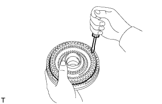
Using a snap ring expander, install the snap ring.
Note
Make sure that the snap ring is firmly installed to the groove.
-
-
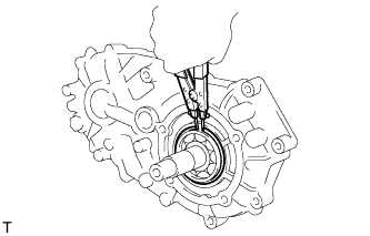
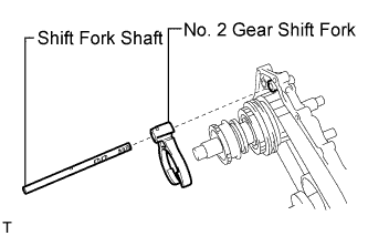
INSTALL TRANSFER HIGH AND LOW SHIFT FORK SHAFT
-
Apply gear oil to the connecting areas of the shift fork shaft and each part.
-
Install the shift fork shaft and No. 2 gear shift fork.
Note
Make sure to install the shift fork shaft and No. 2 gear shift fork in the correct direction.
-
Install the spring and ball to the hole.
-
Apply adhesive to the threads of the plug.
Adhesive Toyota Genuine Adhesive 1344, Three Bond 1344 or equivalent -
Using a hexagon wrench, install the plug.
- Torque:
- 18.6 N*m { 190 kgf*cm, 14 ft.*lbf }
-
-
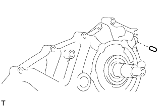
INSTALL FRONT TRANSFER DRIVE SHIFT FORK SHAFT
-
Apply gear oil to the straight pin.
-
Install the straight pin to the hole.
-
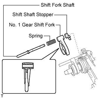
Apply gear oil to the connecting areas of the shift fork shaft and each part.
-
Install the shift fork shaft, No. 1 gear shift fork, spring and shift shaft stopper.
Note
Make sure to install the shift fork shaft, No. 1 gear shift fork and shift shaft stopper in the correct direction.
-
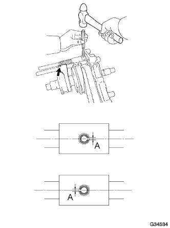
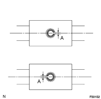
Using a pin punch and hammer, install the 2 slotted pins.
Note
When installing the slotted pins, make sure the pin's groove labeled A is facing in the same direction as the shaft.
-
Install the spring and ball to the hole.
-
Apply adhesive to the threads of the plug.
Adhesive Toyota Genuine Adhesive 1344, Three Bond 1344 or equivalent -
Using a hexagon wrench, install the plug.
- Torque:
- 18.6 N*m { 190 kgf*cm, 14 ft.*lbf }
-
-
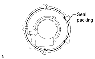
INSTALL REAR TRANSFER CASE
-
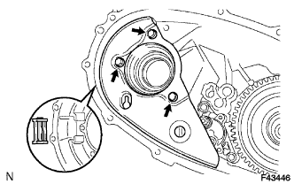
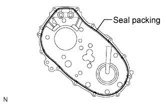
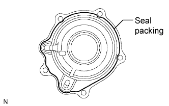
Apply seal packing to the rear case as shown in the illustration.
Seal packing Toyota Genuine Seal Packing 1281, Three Bond 1281 or equivalent Note
If the removed rear case will be reused:
After removing the rear case, be sure to perform the following before reinstalling it: 1) using a knife, cut off any old seal packing on the rear case's contact surface, 2) clean off any remaining old seal packing from the rear case's contact surface, and 3) reapply seal packing to the rear case.
-
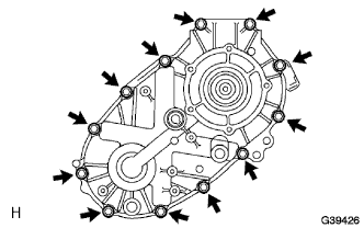
Install the clamp and rear case with the 12 bolts.
- Torque:
- 28 N*m { 285 kgf*cm, 21 ft.*lbf }
Note
Tighten the bolts of the rear case within 10 minutes of applying the seal packing. The seal packing will dry very quickly.
-
-
INSTALL TRANSFER SPEEDOMETER DRIVE GEAR
-
INSTALL TRANSFER OUTPUT SHAFT WASHER
-
Install the 2 output washers.
-
-
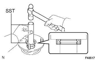
INSTALL TRANSFER COVER OIL SEAL
-
Using SST and a hammer, tap in a new oil seal until its surface is flush with the housing upper surface.
- SST
- 09223-46011
- 09631-32020
Note
Be careful not to damage the extension housing.
-
Coat the lip of the oil seal with MP grease.
-
-
INSTALL TRANSFER EXTENSION HOUSING SUB-ASSEMBLY
-
Apply seal packing to the extension housing as shown in the illustration.
Seal packing Toyota Genuine Seal Packing 1281, Three Bond 1281 or equivalent Note
If the removed extension housing will be reused:
After removing the housing, be sure to perform the following before reinstalling it: 1) using a knife, cut off any old seal packing on the housing's contact surface, 2) clean off any remaining old seal packing from the housing's contact surface, and 3) reapply seal packing to the housing.
-
Apply adhesive to the threads of the bolts.
Adhesive Toyota Genuine Adhesive 1344, Three Bond 1344 or equivalent -
Install the extension housing with the 5 bolts.
- Torque:
- 12 N*m { 22 kgf*cm, 9 ft.*lbf }
Note
Tighten the bolts of the extension housing within 10 minutes of applying the seal packing. The seal packing will dry very quickly.
-
-
INSTALL SPEEDOMETER SENSOR
-
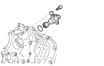
Coat a new O-ring with gear oil and install it to the speedometer sensor.
-
Install the speedometer sensor to the transfer with the bolt.
- Torque:
- 12 N*m { 177 kgf*cm, 8 ft.*lbf }
-
-
INSTALL TRANSFER OUTPUT SHAFT COMPANION FLANGE OIL SEAL (for Front)
-
Using SST and a hammer, tap in a new oil seal.
- SST
- 09950-60010 ( 09951-00320 )
- 09950-70010 ( 09951-07100 )
Note
Be careful not to damage the companion flange.
-
-
INSTALL TRANSFER OUTPUT SHAFT COMPANION FLANGE OIL SEAL (for Rear)
-
Using SST and a hammer, tap in a new oil seal (for rear) in the same way as the oil seal (for front).
- SST
- 09950-60010 ( 09951-00320 )
- 09950-70010 ( 09951-07100 )
Note
Be careful not to damage the companion flange.
-
-
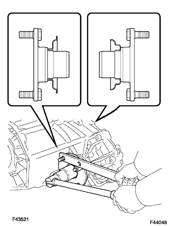
INSTALL OUTPUT SHAFT COMPANION FLANGE SUB-ASSEMBLY (for Front)
-
Apply gear oil to the connecting areas of the companion flange and driven sprocket.
-
Install the companion flange to the driven sprocket.
-
Using SST to hold the companion flange, install a new lock nut.
- SST
- 09330-00021
- 09950-40011 ( 09951-04020, 09952-04010, 09953-04030, 09954-04010, 09955-04051, 09957-04010, 09958-04011 )
- Torque:
- 118 N*m { 1,203 kgf*cm, 87 ft.*lbf }
-
Using a chisel and hammer, stake the lock nut to the driven sprocket.
Note
-
Thoroughly stake the shaft to the lock nut's groove.
-
Be careful not to damage parts around the lock nut.
-
Do not apply excessive force to the shaft.
-
-
-
INSTALL OUTPUT SHAFT COMPANION FLANGE SUB-ASSEMBLY (for Rear)
-
Apply gear oil to the connecting areas of the companion flange and output shaft.
-
Using SST, install the companion flange (rear) in the same way as the companion flange (front).
- SST
- 09330-00021
- 09950-40011 ( 09951-04020, 09952-04010, 09953-04030, 09954-04010, 09955-04051, 09957-04010, 09958-04011 )
- Torque:
- 118 N*m { 1,203 kgf*cm, 87 ft.*lbf }
-
-
INSTALL BREATHER OIL DEFLECTOR SUB-ASSEMBLY
-
INSTALL TRANSFER CONTROL SHIFT LEVER RETAINER SUB-ASSEMBLY (for Transfer on Type)
-
Install the retainer with the 4 bolts.
- Torque:
- 18 N*m { 183 kgf*cm, 13 ft.*lbf }
-
-
INSTALL TRANSFER CASE COVER SUB-ASSEMBLY (for Adapter on Type)
-
Install the case cover with the 4 bolts.
- Torque:
- 18 N*m { 183 kgf*cm, 13 ft.*lbf }
-
-
INSTALL TRANSFER COVER OIL SEAL
-
Using SST and a hammer, tap in a new oil seal until its surface is flush with the bearing retainer upper surface.
- SST
- 09950-60010 ( 09951-00590 )
- 09950-70010 ( 09951-07100 )
Note
Be careful not to damage the bearing retainer.
-
Coat the lip of the oil seal with MP grease.
-
-
INSTALL TRANSFER BEARING RETAINER SUB-ASSEMBLY
-
Apply seal packing to the bearing retainer as shown in the illustration.
Seal packing Toyota Genuine Seal Packing 1281, Three Bond 1281 or equivalent Note
If the removed bearing retainer will be reused:
After removing the retainer, be sure to perform the following before reinstalling it: 1) using a knife, cut off any old seal packing on the retainer's contact surface, 2) clean off any remaining old seal packing from the retainer's contact surface, and 3) reapply seal packing to the retainer.
-
Apply adhesive to the bolt threads.
Adhesive Toyota Genuine Adhesive 1344, Three Bond 1344 or equivalent -
Install the retainer with the 5 bolts.
- Torque:
- 11.5 N*m { 117 kgf*cm, 8 ft.*lbf }
Note
Tighten the bolts of the bearing retainer within 10 minutes of applying the seal packing. The seal packing will dry very quickly.
-
-
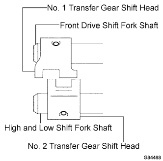
INSTALL TRANSFER GEAR SHIFT HEAD (for Adapter on Type)
-
Install the No. 1 and No. 2 gear shift heads to the front drive shift fork shaft and high and low shift fork shaft.
-
Using a pin punch and hammer, tap in the 2 slotted pins to the No. 1 and No. 2 gear shift heads.
Note
When installing the slotted pins, make sure the pin's groove labeled A is facing in the same direction as the shaft.
-
-
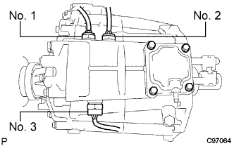
INSTALL TRANSFER INDICATOR SWITCH
-
Install a new gasket and the indicator switch.
- Torque:
- 37 N*m { 377 kgf*cm, 27 ft.*lbf }
Tech Tips
Indicator switch:
No. 1 Indicator switch (neutral position) for A/T No. 2 Indicator switch (L4 position) for A/T or M/T w/ ABS No. 3 Indicator switch (4WD) for A/T and M/T
-