VACUUM REGULATING VALVE (w/ EGR System without EGR Cooler) INSPECTION
Note
Do not remove the electric vacuum regulating valve from the bracket.
-
INSPECT ELECTRIC VACUUM REGULATING VALVE ASSEMBLY (for EGR)
-
Inspect the electric vacuum regulating valve.
-
Measure the resistance according to the value(s) in the table below.
Standard Resistance Tester Connection Condition Specified Condition 1 - 2 20°C (68°F) 11 to 13 Ω 1 - Body ground
2 - Body ground
20°C (68°F) 10 kΩ or higher If the result is not as specified, replace the electric EGR control valve assembly.
-
-
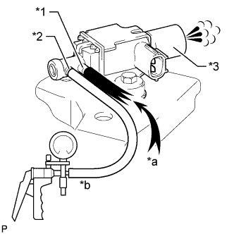
Text in Illustration *1 Port E *2 Port F *3 Filter *a Air *b Vacuum w/ Intercooler:
Check the operation of the electric vacuum regulating valve.
-
When a vacuum of 67 kPa (500 mmHg, 19.7 in.Hg) is applied to port F, check that air flows from port E to the filter.
-
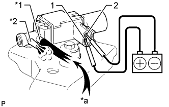
Text in Illustration *1 Port E *2 Port F *a Air Apply battery voltage across terminals 1 and 2.
-
Check that air flows from port E to port F.
If the result is not as specified, replace the electric EGR control valve assembly.
-
-
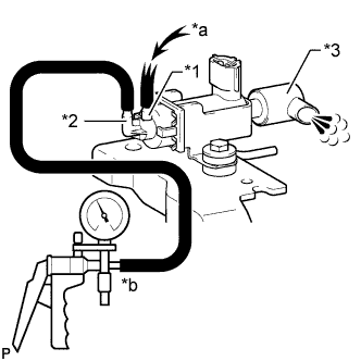
Text in Illustration *1 Port E *2 Port F *3 Filter *a Air *b Vacuum w/o Intercooler:
Check the operation of the electric vacuum regulating valve.
-
When a vacuum of 67 kPa (500 mmHg, 19.7 in.Hg) is applied to port F, check that air flows from port E to the filter.
-
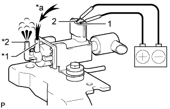
Text in Illustration *1 Port E *2 Port F *a Air Apply battery voltage across terminals 1 and 2.
-
Check that air flows from port E to port F.
If the result is not as specified, replace the electric EGR control valve assembly.
-
-