HEADLIGHT ASSEMBLY(for Triple Beam Headlight) INSPECTION
PROCEDURE
-
INSPECT HEADLIGHT UNIT LH
-
Remove the headlight assembly LH.
-
Remove the headlight unit assembly LH from the headlight assembly LH.
-
Inspect the turn signal light circuit.
-
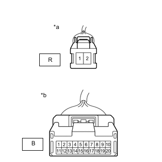
*a Component without harness connected
(to Headlight LED Unit Assembly LH)
*b Component without harness connected
(to Headlight ECU Sub-assembly LH)
Measure the resistance according to the value(s) in the table below.
Standard Resistance Tester Connection Condition Specified Condition R-2 - B-9 Always Below 1 Ω R-1 - B-13 Always Below 1 Ω If the result is not as specified, replace the headlight unit LH.
-
-
Inspect the headlight leveling motor circuit.
-
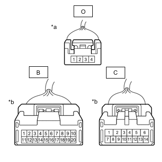
*a Component without harness connected
(to Headlight Leveling Motor LH)
*b Component without harness connected
(to Headlight ECU Sub-assembly LH)
Measure the resistance according to the value(s) in the table below.
Standard Resistance Tester Connection Condition Specified Condition O-1 - B-7 Always Below 1 Ω O-3 - C-13 Always Below 1 Ω O-4 - B-17 Always Below 1 Ω If the result is not as specified, replace the headlight unit LH.
-
-
Inspect the high beam headlight circuit. (w/o Adaptive High Beam System)
-
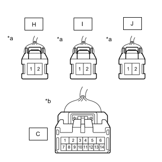
*a Component without harness connected
(to Headlight Unit Assembly LH)
*b Component without harness connected
(to Headlight ECU Sub-assembly LH)
Measure the resistance according to the value(s) in the table below.
Standard Resistance Tester Connection Condition Specified Condition C-8 - H-2 Always Below 1 Ω H-1 - I-2 Always Below 1 Ω I-1 - J-2 Always Below 1 Ω C-7 - J-1 Always Below 1 Ω If the result is not as specified, replace the headlight unit LH.
-
-
Inspect the add high beam headlight circuit. (w/ Adaptive High Beam System)
-
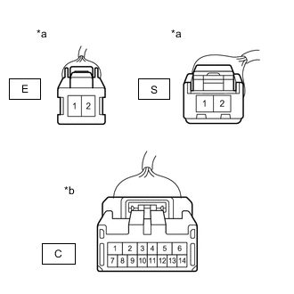
*a Component without harness connected
(to Headlight Unit Assembly LH)
*b Component without harness connected
(to Headlight ECU Sub-assembly LH)
Measure the resistance according to the value(s) in the table below.
Standard Resistance Tester Connection Condition Specified Condition C-8 - S-2 Always Below 1 Ω S-1 - E-2 Always Below 1 Ω C-7 - E-1 Always Below 1 Ω If the result is not as specified, replace the headlight unit LH.
-
-
Inspect the low beam headlight circuit.
-

*a Component without harness connected
(to Headlight Unit Assembly LH)
*b Component without harness connected
(to Headlight ECU Sub-assembly LH)
Measure the resistance according to the value(s) in the table below.
Standard Resistance Tester Connection Condition Specified Condition B-3 - G-1 Always Below 1 Ω B-4 - G-2 Always Below 1 Ω If the result is not as specified, replace the headlight unit LH.
-
-
Inspect the headlight fan circuit.
-
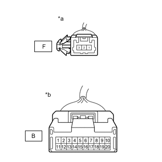
*a Component without harness connected
(to Headlight Fan LH)
*b Component without harness connected
(to Headlight ECU Sub-assembly LH)
Measure the resistance according to the value(s) in the table below.
Standard Resistance Tester Connection Condition Specified Condition B-6 - F-1 Always Below 1 Ω B-15 - F-3 Always Below 1 Ω B-14 - F-2 Always Below 1 Ω If the result is not as specified, replace the headlight unit LH.
-
-
Inspect the clearance light / daytime running light circuit.
-
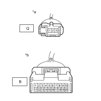
*a Component without harness connected
(to Headlight LED Unit Assembly LH)
*b Component without harness connected
(to Headlight ECU Sub-assembly LH)
Measure the resistance according to the value(s) in the table below.
Standard Resistance Tester Connection Condition Specified Condition B-20 - Q-2 Always Below 1 Ω B-16 - Q-3 Always Below 1 Ω B-11 - Q-1 Always Below 1 Ω If the result is not as specified, replace the headlight unit LH.
-
-
Inspect the LED array circuit. (w/ Adaptive High Beam System)
-
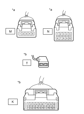
*a Component without harness connected
(to Headlight Unit Assembly LH (LED Array))
*b Component without harness connected
(to Headlight Light Control ECU Sub-assembly LH)
Measure the resistance according to the value(s) in the table below.
Standard Resistance Tester Connection Condition Specified Condition K-2 - M-1 Always Below 1 Ω K-3 - M-2 Always Below 1 Ω K-11 - M-3 Always Below 1 Ω K-12 - M-4 Always Below 1 Ω K-12 - N-1 Always Below 1 Ω K-13 - N-2 Always Below 1 Ω K-14 - N-3 Always Below 1 Ω K-15 - N-4 Always Below 1 Ω K-16 - N-5 Always Below 1 Ω K-17 - N-6 Always Below 1 Ω K-18 - N-7 Always Below 1 Ω K-19 - N-8 Always Below 1 Ω K-20 - N-9 Always Below 1 Ω M-5 - T-1 Always Below 1 Ω N-10 - T-1 Always Below 1 Ω If the result is not as specified, replace the headlight unit LH.
-
-
Inspect the LED array fan circuit. (w/ Adaptive High Beam System)
-
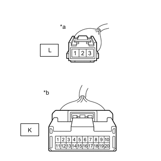
*a Component without harness connected
(to Headlight Unit Assembly LH (LED Array Fan LH))
*b Component without harness connected
(to Headlight Light Control ECU Sub-assembly LH)
Measure the resistance according to the value(s) in the table below.
Standard Resistance Tester Connection Condition Specified Condition K-5 - L-1 Always Below 1 Ω K-6 - L-2 Always Below 1 Ω K-7 - L-3 Always Below 1 Ω If the result is not as specified, replace the headlight unit LH.
-
-
Inspect the headlight light control ECU sub-assembly power source and communication circuit. (w/ Adaptive High Beam System)
-
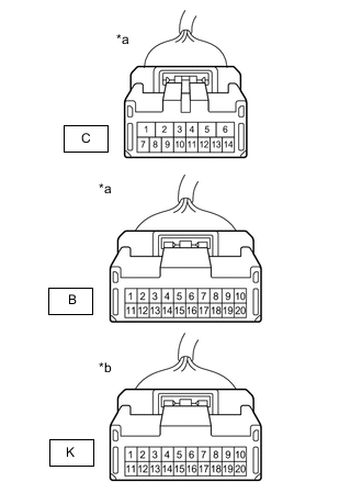
*a Component without harness connected
(to Headlight ECU Sub-assembly LH)
*b Component without harness connected
(to Headlight Light Control ECU Sub-assembly LH)
Measure the resistance according to the value(s) in the table below.
Standard Resistance Tester Connection Condition Specified Condition K-10 - B-10 Always Below 1 Ω K-1 - B-1 Always Below 1 Ω C-13 - K-9 Always Below 1 Ω If the result is not as specified, replace the headlight unit LH.
-
-
-
INSPECT HEADLIGHT UNIT RH
-
Remove the headlight assembly RH.
-
Remove the headlight unit assembly RH from the headlight assembly RH.
-
Inspect the turn signal light circuit.
-
*a Component without harness connected
(to Headlight LED Unit Assembly RH)
*b Component without harness connected
(to Headlight ECU Sub-assembly RH)
Measure the resistance according to the value(s) in the table below.
Standard Resistance Tester Connection Condition Specified Condition R-2 - B-9 Always Below 1 Ω R-1 - B-13 Always Below 1 Ω If the result is not as specified, replace the headlight unit RH.
-
-
Inspect the headlight leveling motor circuit.
-
*a Component without harness connected
(to Headlight Leveling Motor RH)
*b Component without harness connected
(to Headlight ECU Sub-assembly RH)
Measure the resistance according to the value(s) in the table below.
Standard Resistance Tester Connection Condition Specified Condition O-1 - B-7 Always Below 1 Ω O-3 - C-13 Always Below 1 Ω O-4 - B-17 Always Below 1 Ω If the result is not as specified, replace the headlight unit RH.
-
-
Inspect the high beam headlight circuit. (w/o Adaptive High Beam System)
-
*a Component without harness connected
(to Headlight Unit Assembly RH)
*b Component without harness connected
(to Headlight ECU Sub-assembly RH)
Measure the resistance according to the value(s) in the table below.
Standard Resistance Tester Connection Condition Specified Condition C-8 - H-2 Always Below 1 Ω H-1 - I-2 Always Below 1 Ω I-1 - J-2 Always Below 1 Ω C-7 - J-1 Always Below 1 Ω If the result is not as specified, replace the headlight unit RH.
-
-
Inspect the add high beam headlight circuit. (w/ Adaptive High Beam System)
-
*a Component without harness connected
(to Headlight Unit Assembly RH)
*b Component without harness connected
(to Headlight ECU Sub-assembly RH)
Measure the resistance according to the value(s) in the table below.
Standard Resistance Tester Connection Condition Specified Condition C-8 - S-2 Always Below 1 Ω S-1 - E-2 Always Below 1 Ω C-7 - E-1 Always Below 1 Ω If the result is not as specified, replace the headlight unit RH.
-
-
Inspect the low beam headlight circuit.
-
*a Component without harness connected
(to Headlight Unit Assembly RH)
*b Component without harness connected
(to Headlight ECU Sub-assembly RH)
Measure the resistance according to the value(s) in the table below.
Standard Resistance Tester Connection Condition Specified Condition B-3 - G-1 Always Below 1 Ω B-4 - G-2 Always Below 1 Ω If the result is not as specified, replace the headlight unit RH.
-
-
Inspect the headlight fan circuit.
-
*a Component without harness connected
(to Headlight Fan RH)
*b Component without harness connected
(to Headlight ECU Sub-assembly RH)
Measure the resistance according to the value(s) in the table below.
Standard Resistance Tester Connection Condition Specified Condition B-6 - F-1 Always Below 1 Ω B-15 - F-3 Always Below 1 Ω B-14 - F-2 Always Below 1 Ω If the result is not as specified, replace the headlight unit RH.
-
-
Inspect the clearance light / daytime running light circuit.
-
*a Component without harness connected
(to Headlight LED Unit Assembly RH)
*b Component without harness connected
(to Headlight ECU Sub-assembly RH)
Measure the resistance according to the value(s) in the table below.
Standard Resistance Tester Connection Condition Specified Condition B-20 - Q-2 Always Below 1 Ω B-16 - Q-3 Always Below 1 Ω B-11 - Q-1 Always Below 1 Ω If the result is not as specified, replace the headlight unit RH.
-
-
Inspect the LED array circuit. (w/ Adaptive High Beam System)
-
*a Component without harness connected
(to Headlight Unit Assembly RH (LED Array RH))
*b Component without harness connected
(to Headlight Light Control ECU Sub-assembly RH)
Measure the resistance according to the value(s) in the table below.
Standard Resistance Tester Connection Condition Specified Condition K-2 - M-1 Always Below 1 Ω K-3 - M-2 Always Below 1 Ω K-11 - M-3 Always Below 1 Ω K-12 - M-4 Always Below 1 Ω K-12 - N-1 Always Below 1 Ω K-13 - N-2 Always Below 1 Ω K-14 - N-3 Always Below 1 Ω K-15 - N-4 Always Below 1 Ω K-16 - N-5 Always Below 1 Ω K-17 - N-6 Always Below 1 Ω K-18 - N-7 Always Below 1 Ω K-19 - N-8 Always Below 1 Ω K-20 - N-9 Always Below 1 Ω M-5 - T-1 Always Below 1 Ω N-10 - T-1 Always Below 1 Ω If the result is not as specified, replace the headlight unit RH.
-
-
Inspect the LED array fan circuit. (w/ Adaptive High Beam System)
-
*a Component without harness connected
(to Headlight Unit Assembly RH (LED Array Fan))
*b Component without harness connected
(to Headlight Light Control ECU Sub-assembly RH)
Measure the resistance according to the value(s) in the table below.
Standard Resistance Tester Connection Condition Specified Condition K-5 - L-1 Always Below 1 Ω K-6 - L-2 Always Below 1 Ω K-7 - L-3 Always Below 1 Ω If the result is not as specified, replace the headlight unit RH.
-
-
Inspect the headlight light control ECU sub-assembly power source and communication circuit. (w/ Adaptive High Beam System)
-
*a Component without harness connected
(to Headlight ECU Sub-assembly RH)
*b Component without harness connected
(to Headlight Light Control ECU Sub-assembly RH)
Measure the resistance according to the value(s) in the table below.
Standard Resistance Tester Connection Condition Specified Condition K-10 - B-10 Always Below 1 Ω K-1 - B-1 Always Below 1 Ω C-13 - K-9 Always Below 1 Ω If the result is not as specified, replace the headlight unit RH.
-
-