FRONT DOOR ADJUSTMENT
CAUTION / NOTICE / HINT
Use the same procedure for the RH and LH sides.
The procedure listed below is for the LH side.
-
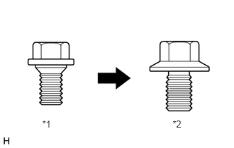
*1
Centering Bolt
*2
Standard Bolt
Centering bolts are used to mount the door hinge to the vehicle body and door. The door cannot be adjusted with the centering bolts on. Substitute the centering bolts for standard bolts when making adjustments.
A bolt without a torque specification is shown in the standard bolt chart.
PROCEDURE
INSPECT FRONT DOOR PANEL SUB-ASSEMBLY LH
Check that the clearance measurements of areas A to L are within the standard ranges.
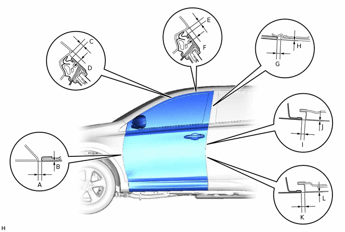
Table 1. Standard Clearance Area
Measurement
Area
Measurement
A
2.2 to 5.2 mm (0.0866 to 0.205 in.)
B
-1.5 to 1.5 mm (0.0591 to 0.0591 in.)
C
3.7 to 6.7 mm (0.146 to 0.264 in.)
D
4.5 to 7.5 mm (0.177 to 0.295 in.)
E
3.7 to 6.7 mm (0.146 to 0.264 in.)
F
4.2 to 7.2 mm (0.165 to 0.283 in.)
G
(Reference)
2.5 to 6.5 mm (0.0984 to 0.259 in.)
H
-2.0 to 2.0 mm (-0.0787 to 0.0787 in.)
I
2.9 to 5.3 mm (0.114 to 0.209 in.)
J
-1.2 to 1.2 mm (-0.0472 to 0.0472 in.)
K
2.9 to 5.3 mm (0.114 to 0.209 in.)
L
-1.2 to 1.2 mm (-0.0472 to 0.0472 in.)
ADJUST FRONT DOOR PANEL SUB-ASSEMBLY LH
-
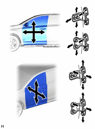
Using SST, loosen the hinge bolts on the body and adjust the door position.
09812-00010
Tighten the hinge bolts on the body after the adjustment.
26 N*m
265 kgf*cm
19 ft.*lbf
Loosen the hinge bolts on the door and adjust the door position.
Tighten the hinge bolts on the door after the adjustment.
26 N*m
265 kgf*cm
19 ft.*lbf
-
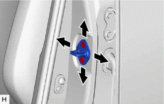
Using a T40 "TORX" socket, adjust the striker position by slightly loosening the striker mounting screws and hitting the striker with a plastic-faced hammer.
Using a T40 "TORX" socket, tighten the striker mounting screws after the adjustment.
23 N*m
235 kgf*cm
17 ft.*lbf
-
CONNECT CABLE TO NEGATIVE BATTERY TERMINAL (w/ Side Airbag)
Note:When disconnecting the cable, some systems need to be initialized after the cable is reconnected.
CHECK SRS WARNING LIGHT (w/ Side Airbag)