REAR AXLE CARRIER REMOVAL
CAUTION / NOTICE / HINT
Use the same procedure for the RH and LH sides.
The procedure listed below is for the LH side.
PROCEDURE
REMOVE REAR WHEEL
REMOVE REAR AXLE HUB AND BEARING ASSEMBLY LH
REMOVE REAR STABILIZER LINK ASSEMBLY LH
DISCONNECT NO. 3 PARKING BRAKE CABLE ASSEMBLY
-
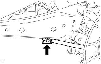
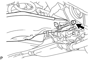
Remove the bolt and disconnect the No. 3 parking brake cable assembly from the rear trailing arm assembly.
-
DISCONNECT PARKING BRAKE ASSEMBLY
-
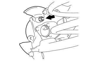
Remove the nut and disconnect the parking brake assembly from the rear axle carrier.
-
REMOVE REAR SUSPENSION ARM COVER LH (w/ Cover)
REMOVE REAR HEIGHT CONTROL SENSOR SUB-ASSEMBLY LH
DISCONNECT REAR SHOCK ABSORBER BRACKET LH
-
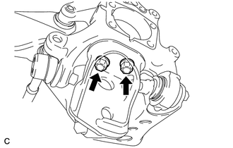
Remove the 2 bolts and disconnect the rear shock absorber bracket LH from the rear axle carrier.
-
DISCONNECT REAR NO. 1 SUSPENSION ARM ASSEMBLY LH
-
Remove the nut from the axle carrier.
-
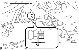
*a
1 mm (0.0394 in.)
Install SST to the rear No. 1 suspension arm assembly LH as shown in the illustration.
09960-20010
09961-02060
Note:Make sure that the clearance measurement between SST and the rear axle assembly is 1 mm (0.0394 in.).
Tip:Use 2 SST of the same type.
Using SST, disconnect the rear No. 1 suspension arm assembly LH from the rear axle carrier as shown in the illustration.
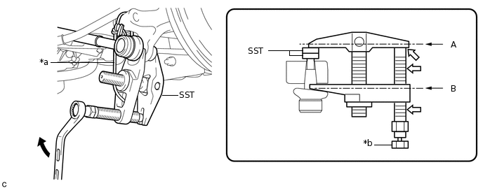
*a
Tie the string without any slack.
*b
Place a wrench here.

Turn

Molybdenum Grease Application Area
09960-20010
09961-02010
CAUTION:Apply molybdenum grease to the threads and end of SST bolt.
Note:Be sure to tighten the string firmly to secure SST to the rear axle assembly to prevent SST from falling off.
Install SST so that A and B are parallel.
Be sure to place a wrench on the part indicated in the illustration.
Do not damage the ball joint dust cover.
-
DISCONNECT REAR TRAILING ARM ASSEMBLY
-
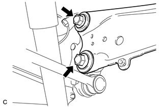
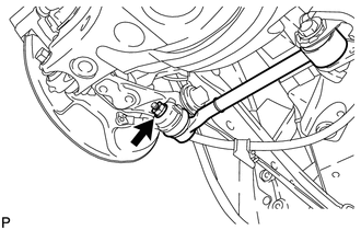
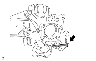
Remove the 2 bolts and disconnect the rear trailing arm assembly from the rear axle carrier.
-
DISCONNECT REAR NO. 2 SUSPENSION ARM ASSEMBLY LH
-
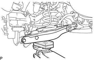
Support the rear No. 2 suspension arm assembly LH with a jack using a wooden block to avoid damage.
Note:Do not excessively jack up the rear No. 2 suspension arm assembly LH.
Tip:Support the rear shock absorber at a position where it compresses by approximately 20 to 30 mm (0.788 to 1.181 in.).
-
Loosen the bolt and nut of the rear No. 2 suspension arm assembly LH on the rear suspension member side.
-
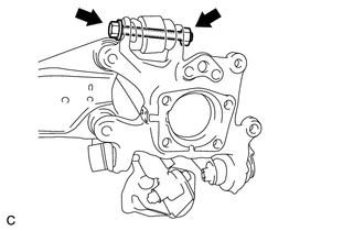
Remove the bolt and disconnect the No. 2 rear suspension arm assembly LH from the rear axle carrier.
Lower the jack gradually to remove the rear coil spring together with the rear upper coil spring insulator.
Remove the rear lower coil spring insulator from the rear No. 2 suspension arm assembly LH.
-
REMOVE REAR AXLE CARRIER SUB-ASSEMBLY LH
-
Remove the bolt and the rear axle carrier sub-assembly LH.
-