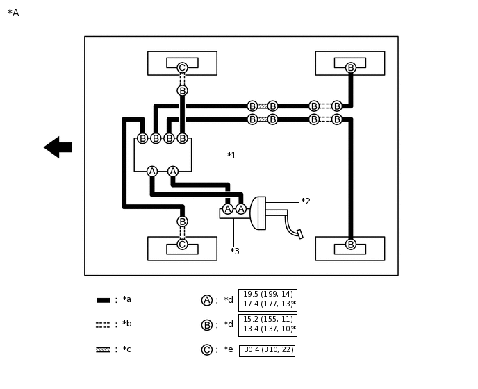
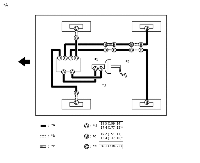
BRAKE LINE SYSTEM DIAGRAM
Tip:
See the layout drawing to confirm the locations and tightening torque of flexible hoses and brake lines.
*A |
for LHD |
- |
- |
*1 |
Brake Actuator Assembly |
*2 |
Brake Booster Assembly |
*3 |
Brake Master Cylinder Sub-assembly |
- |
- |
*a |
Brake Line |
*b |
Flexible Hose |
*c |
Brake Tube Way |
*d |
Union Nut |
*e |
Union Bolt |
- |
- |
 |
N*m (kgf*cm, ft.*lbf): Specified torque |
* |
For use with a union nut wrench |
 |
Front |
- |
- |
*A |
for RHD |
- |
- |
*1 |
Brake Actuator Assembly |
*2 |
Brake Booster Assembly |
*3 |
Brake Master Cylinder Sub-assembly |
- |
- |
*a |
Brake Line |
*b |
Flexible Hose |
*c |
Brake Tube Way |
*d |
Union Nut |
*e |
Union Bolt |
- |
- |
|
N*m (kgf*cm, ft.*lbf): Specified torque |
* |
For use with a union nut wrench |
|
Front |
- |
- |