ENTRY AND START SYSTEM(for Start Function), Diagnostic DTC:B2275
| DTC Code | DTC Name |
|---|---|
| B2275 | STSW Monitor Malfunction |
DESCRIPTION
This DTC is stored when a malfunction is detected in the starter circuit inside the certification ECU (smart key ECU assembly).
Tech Tips
-
When the certification ECU (smart key ECU assembly) is replaced with a new one and the cable is connected to the negative (-) auxiliary battery terminal, the power source mode changes to on (IG).
-
When the auxiliary battery cable is disconnected and reconnected, the power source returns to the mode it was in before the auxiliary battery cable was disconnected.
| DTC No. | DTC Detection Condition | Trouble Area |
|---|---|---|
| B2275 | Certification ECU (smart key ECU assembly) internal HV activation request output circuit malfunction or external circuit malfunction. |
|
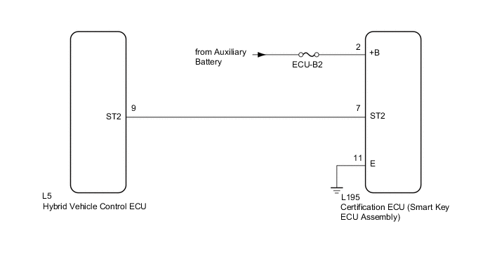
WIRING DIAGRAM
CAUTION / NOTICE / HINT
Note
-
The entry and start system uses multiplex communication. First perform the inspections in "How to Proceed with Troubleshooting" to confirm that there are no communication malfunctions before proceeding with troubleshooting Click here.
-
Inspect the fuses for circuits related to this system before performing the following inspection procedure.
-
After performing repairs, perform the operation that fulfills the DTC output confirmation operation, and then confirm that no DTCs are output again.
PROCEDURE
-
CHECK HARNESS AND CONNECTOR ((POWER SOURCE)
-
Disconnect the L195 certification ECU (smart key ECU assembly) connector.
-
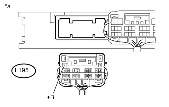
Text in Illustration *a Rear view of wire harness connector
(to Certification ECU (Smart Key ECU Assembly))
Measure the voltage according to the value(s) in the table below.
Standard Voltage Tester Connection Condition Specified Condition L195-2 (+B) - Body ground Power switch off 11 to 14 V
NG 
REPAIR OR REPLACE HARNESS OR CONNECTOR
OK 
-
-
CHECK HARNESS AND CONNECTOR (GROUND)
-
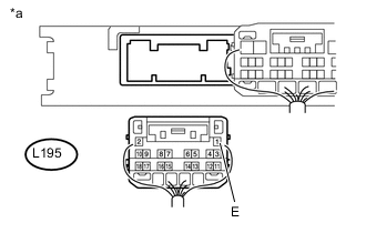
Text in Illustration *a Rear view of wire harness connector
(to Certification ECU (Smart Key ECU Assembly))
Measure the resistance according to the value(s) in the table below.
Standard Resistance Tester Connection Condition Specified Condition L195-11 (E) - Body ground Always Below 1 Ω
NG
REPAIR OR REPLACE HARNESS OR CONNECTOR
OK
-
-
CHECK HARNESS AND CONNECTOR CERTIFICATION ECU (SMART KEY ECU ASSEMBLY) - HYBRID VEHICLE CONTROL ECU)
-
Disconnect the L195 certification ECU (smart key ECU assembly) connector.
-
Disconnect the L5 hybrid vehicle control ECU connector.
-
Measure the resistance according to the value(s) in the table below.
Standard Resistance Tester Connection Condition Specified Condition L195-7 (ST2) - L5-9 (ST2) Always Below 1 Ω L195-7 (ST2) or L5-9 (ST2) - Body ground Always 10 kΩ or higher
NG
REPAIR OR REPLACE HARNESS OR CONNECTOR
OK
-
-
CHECK CERTIFICATION ECU (SMART KEY ECU ASSEMBLY)
-
Reconnect the L195 certification ECU (smart key ECU assembly) connector.
-
Reconnect the L5 hybrid vehicle control ECU connector.
-
Measure the voltage according to the value(s) in the table below.
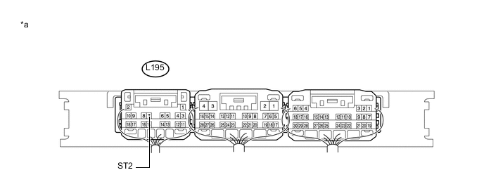
Standard Voltage Tester Connection Condition Specified Condition L195-7 (ST2) - Body ground With the brake pedal depressed, the power switch is pressed and held → After approx. 3 sec. has elapsed, the power switch is released 9 V or higher → 1 V or less Text in Illustration *a Component with harness connected
(to Certification ECU (Smart Key ECU Assembly))
- -
OK
REPLACE HYBRID VEHICLE CONTROL ECU Click here
NG
REPLACE CERTIFICATION ECU (SMART KEY ECU ASSEMBLY)
-