MONOLITHIC CONVERTER REMOVAL
CAUTION / NOTICE / HINT
The necessary procedures (adjustment, calibration, initialization or registration) that must be performed after parts are removed and installed, or replaced during exhaust manifold converter sub-assembly removal/installation are shown below.
| Replaced Part or Performed Procedure | Necessary Procedure | Effect/Inoperative Function when Necessary Procedure not Performed | Link |
|---|---|---|---|
|
Inspection After Repair |
|
Click here for Rear Air Fuel Ratio Sensor Click here for Rear Heated Oxygen Sensor |
CAUTION:
-
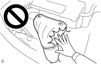
To prevent burns, do not touch the engine, exhaust manifold or other high temperature components while the engine is hot.
-
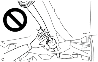
To prevent burns, do not touch the engine, exhaust pipe or other high temperature components while the engine is hot.
PROCEDURE
-
REMOVE FRONT WHEEL OPENING EXTENSION PAD LH
-
REMOVE FRONT WHEEL OPENING EXTENSION PAD RH
-
REMOVE NO. 3 ENGINE UNDER COVER
-
REMOVE NO. 1 ENGINE UNDER COVER
-
REMOVE FRONT EXHAUST PIPE ASSEMBLY
CAUTION:
To prevent burns, do not touch the engine, exhaust pipe or other high temperature components while the engine is hot.
-
w/ Canister Pump Module:
-
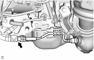
Disconnect the air fuel ratio sensor connector.
-
Disengage the wire harness clamp.
-
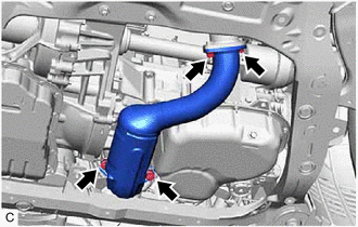
Remove the 2 bolts, 2 compression springs, 2 nuts and front exhaust pipe assembly from the exhaust manifold converter sub-assembly and center exhaust pipe assembly.
-
Remove the 2 exhaust pipe gaskets from the exhaust manifold converter sub-assembly and front exhaust pipe assembly.
-
-
w/o Canister Pump Module:
-
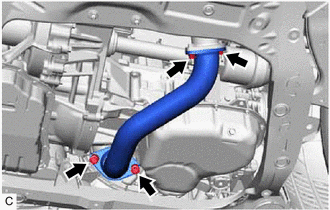
Remove the 2 bolts, 2 compression springs, 2 nuts and front exhaust pipe assembly from the exhaust manifold converter sub-assembly and center exhaust pipe assembly.
-
Remove the 2 exhaust pipe gaskets from the exhaust manifold converter sub-assembly and front exhaust pipe assembly.
-
-
-
REMOVE NO. 1 ENGINE COVER SUB-ASSEMBLY
-
REMOVE AIR CLEANER CAP WITH AIR CLEANER HOSE
-
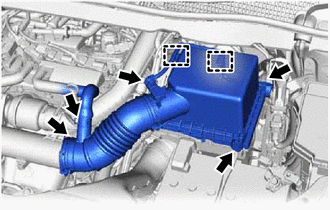
Disconnect the intake mass air flow meter sub-assembly connector.
-
Disengage the 2 wire harness clamps from the air cleaner cap sub-assembly.
-
Slide the clip and disconnect the ventilation hose from the air cleaner hose.
-
Disengage the 2 clamps and remove the air cleaner cap with air cleaner hose from the air cleaner case sub-assembly.
-
Loosen the hose clamp and remove the air cleaner cap with air cleaner hose from the intake air connector.
-
-
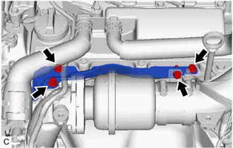
REMOVE INTAKE AIR CONNECTOR
-
w/ Differential Pressure Sensor:
-
Remove the differential pressure sensor.
-
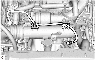
Disengage the 2 wire harness clamps.
-
-
Remove the 2 bolts and disconnect the intake air connector from the outlet compressor elbow and No. 1 air tube.
-
Loosen the hose clamp and remove the intake air connector from the No. 2 air cleaner hose.
-
-
REMOVE NO. 2 AIR CLEANER HOSE
-
Slide the clip and disconnect the No. 4 ventilation hose from the No. 2 air cleaner hose.
-
Loosen the hose clamp and remove the No. 2 air cleaner hose from the inlet compressor elbow.
-
-
REMOVE NO. 5 EXHAUST MANIFOLD HEAT INSULATOR
-
Remove the 4 bolts and No. 5 exhaust manifold heat insulator from the outlet compressor elbow and camshaft housing sub-assembly.
-
-
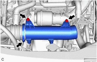
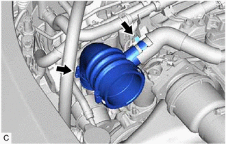
REMOVE OUTLET COMPRESSOR ELBOW
-
Disengage the 2 clamps and disconnect the vacuum transmitting hose assembly from the outlet compressor elbow.
-
Remove the 3 bolts, 2 nuts and outlet compressor elbow from the intake air resonator and turbocharger sub-assembly.
-
Remove the outlet compressor gasket from the turbocharger sub-assembly.
-
Remove the air tube gasket from the intake air resonator.
-
-
REMOVE INTAKE AIR RESONATOR
-
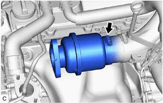
Loosen the hose clamp and remove the intake air resonator from the No. 1 air hose.
-
-
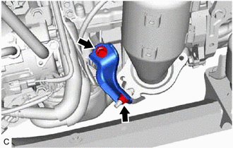
REMOVE NO. 1 VACUUM PIPE (w/ Differential Pressure Sensor)
-
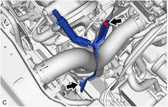
Remove the bolt and disconnect the No. 1 vacuum pipe from the turbocharger stay.
-
Using a 14 mm union nut wrench, disconnect the No. 1 vacuum pipe from the exhaust manifold converter sub-assembly.
-
-
REMOVE AIR FUEL RATIO SENSOR
-
REMOVE NO. 1 EXHAUST MANIFOLD HEAT INSULATOR
CAUTION:
To prevent burns, do not touch the engine, exhaust manifold or other high temperature components while the engine is hot.
-
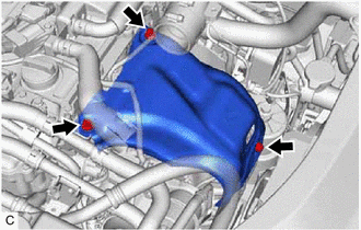
Remove the 3 bolts and No. 1 exhaust manifold heat insulator from the cylinder head sub-assembly and exhaust manifold converter sub-assembly.
-
-
REMOVE NO. 2 EXHAUST MANIFOLD HEAT INSULATOR
CAUTION:
To prevent burns, do not touch the engine, exhaust manifold or other high temperature components while the engine is hot.
-
for Rear Air Fuel Ratio Sensor:
-
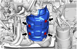
Remove the 4 bolts and No. 2 exhaust manifold heat insulator from the exhaust manifold converter sub-assembly.
-
-
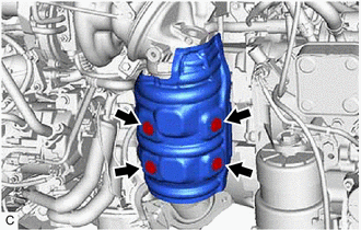
for Rear Heated Oxygen Sensor:
-
Remove the 4 bolts and No. 2 exhaust manifold heat insulator from the exhaust manifold converter sub-assembly.
-
-
-
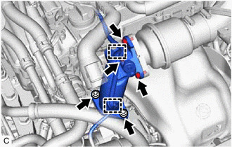
REMOVE EXHAUST MANIFOLD CONVERTER SUB-ASSEMBLY
CAUTION:
To prevent burns, do not touch the engine, exhaust manifold or other high temperature components while the engine is hot.
-
Remove the bolt, nut and manifold stay from the exhaust manifold converter sub-assembly and stiffening crankcase assembly.
-
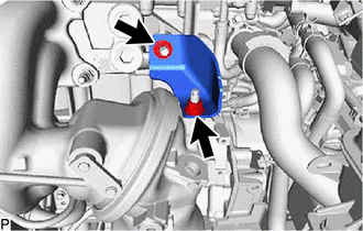
Remove the 2 nuts and turbocharger stay from the exhaust manifold converter sub-assembly and cylinder head sub-assembly.
-
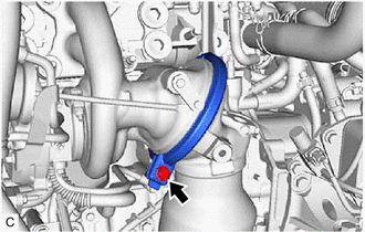
While supporting the exhaust manifold converter sub-assembly to prevent it from falling, loosen the exhaust pipe clamp and remove the exhaust manifold converter sub-assembly.
-
Remove the exhaust pipe clamp from the turbocharger sub-assembly.
-
Remove the outlet turbine elbow gasket from exhaust manifold converter sub-assembly.
-
-
REMOVE STUD BOLT
CAUTION:
To prevent burns, do not touch the engine, exhaust manifold or other high temperature components while the engine is hot.
Tech Tips
If a stud bolt is deformed or its threads are damaged, replace it.
-
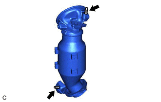
Using an E10 "TORX" socket wrench, remove the 2 stud bolts from the exhaust manifold converter sub-assembly.
-