FRONT LOWER SUSPENSION ARM(for 2AR-FE LH Side) INSTALLATION
PROCEDURE
-
INSTALL FRONT LOWER NO. 1 SUSPENSION ARM SUB-ASSEMBLY LH
-
Install the front lower arm bushing stopper to the front lower No. 1 suspension arm sub-assembly LH.
-
Temporarily install the front lower No. 1 suspension arm sub-assembly LH to the front frame assembly with the 3 bolts and nut.
-
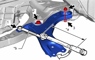
*a Torque Wrench Fulcrum Length *b Ball Joint Lock Nut Wrench 
Turn Using a ball joint lock nut wrench, fully tighten the bolt (1).
- Torque:
- Specified tightening torque
- 200 N*m { 2039 kgf*cm, 148 ft.*lbf }
Tech Tips
-
Calculate the torque wrench reading when changing the fulcrum length of the torque wrench.
-
When using a ball joint lock nut wrench (fulcrum length of 150 mm (5.91 in.)) + torque wrench (fulcrum length of 400 mm (1.31 ft.)):
145.5 N*m (1484 kgf*cm, 107 ft.*lbf)
-
Fully tighten the bolt (2) and then (3).
- Torque:
- Bolt (2)
- 200 N*m { 2039 kgf*cm, 148 ft.*lbf }
- Bolt (3)
- 135 N*m { 1377 kgf*cm, 100 ft.*lbf }
Note
Because the nut has its own stopper, do not turn the nut. Tighten the bolt with the nut secured.
-
Slowly lower the engine assembly with transaxle using a jack and a wooden block.
Note
-
Do not position the wooden block under the oil pan.
-
Do not damage the components surrounding the engine assembly with transaxle.
-
Ensure that the jack and wooden block are stable.
-
-
Connect the engine mounting insulator LH to the engine mounting bracket sub-assembly LH with the bolt and nut.
- Torque:
- 42 N*m { 428 kgf*cm, 31 ft.*lbf }
-
-
CONNECT FRONT ENGINE MOUNTING INSULATOR
-
Connect the front engine mounting insulator to the front frame assembly with the 3 nuts.
- Torque:
- 72 N*m { 734 kgf*cm, 53 ft.*lbf }
-
-
CONNECT FRONT LOWER NO. 1 SUSPENSION ARM SUB-ASSEMBLY LH
-
Connect the front lower No. 1 suspension arm sub-assembly LH to the front lower ball joint assembly LH with the bolt and 2 nuts.
- Torque:
- 92 N*m { 938 kgf*cm, 68 ft.*lbf }
-
-
INSTALL BATTERY CLAMP SUB-ASSEMBLY
-
INSTALL BATTERY
-
INSTALL AIR CLEANER ASSEMBLY
-
INSTALL FRONT FENDER APRON SEAL LH
-
INSTALL NO. 1 ENGINE UNDER COVER
-
INSTALL FRONT WHEEL OPENING EXTENSION PAD LH
-
INSTALL FRONT WHEEL OPENING EXTENSION PAD RH
-
INSTALL FRONT WHEEL
-
INSPECT AND ADJUST FRONT WHEEL ALIGNMENT
-
PERFORM INITIALIZATION
Parking assist monitor system Click here for Initialization
Click here for Calibration
Lighting System (EXT) (w/ Automatic Headlight Beam Level Control System)