SEAT HEATER SYSTEM TERMINALS OF ECU
-
CHECK AIR CONDITIONING AMPLIFIER ASSEMBLY (for Automatic Air Conditioning System with Top-mounted Air Conditioner Pressure Sensor)
-
Disconnect the air conditioning amplifier assembly connector.
-
Measure the voltage and resistance according to the value(s) in the table below.
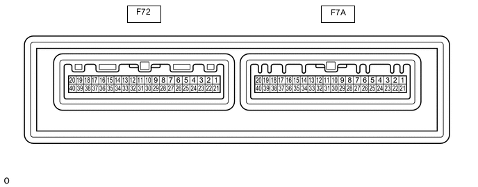
Tester Connection Wiring Color Terminal Description Condition Specified Condition F72-5 (IG+) - Body ground B - Body ground IG power supply Ignition switch ON 11 to 14 V Ignition switch off Below 1 V F72-29 (GND) - Body ground W-B - Body ground Ground Always Below 1 Ω F72-1 (B) - Body ground V - Body ground Battery power supply Always 11 to 14 V -
Reconnect the air conditioning amplifier assembly connector.
-
Check for pulse generation according to the value(s) in the table below.
Tester Connection Wiring Color Terminal Description Condition Specified Condition F72-3 (LIN1) - Body ground L - Body ground Seat heater switch signal Ignition switch ON Pulse generation
-
-
CHECK AIR CONDITIONING AMPLIFIER ASSEMBLY (for Automatic Air Conditioning System with Side-mounted Air Conditioner Pressure Sensor)
-
Disconnect the air conditioning amplifier assembly connector.
-
Measure the voltage and resistance according to the value(s) in the table below.
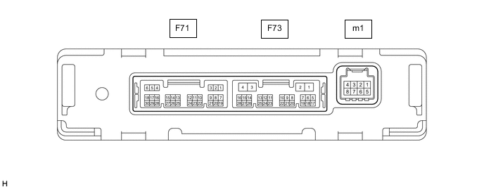
Tester Connection Wiring Color Terminal Description Condition Specified Condition F73-2 (IG+) - Body ground B - Body ground IG power supply Ignition switch ON 11 to 14 V Ignition switch off Below 1 V F73-4 (GND) - Body ground W-B - Body ground Ground Always Below 1 Ω F73-1 (B) - Body ground V - Body ground Battery power supply Always 11 to 14 V -
Reconnect the air conditioning amplifier assembly connector.
-
Check for pulse generation according to the value(s) in the table below.
Tester Connection Wiring Color Terminal Description Condition Specified Condition F73-14 (LIN1) - Body ground BE - Body ground Seat heater switch signal Ignition switch ON Pulse generation
-
-
CHECK AIR CONDITIONING CONTROL ASSEMBLY

-
Disconnect the air conditioning control assembly connector.
-
Measure the voltage and resistance according to the value(s) in the table below.
Tester Connection Wiring Color Terminal Description Condition Specified Condition F61-16 (GND) - Body ground W-B - Body ground Ground Always Below 1 Ω F61-10 (IG+) - F61-16 (GND) BE - W-B IG power supply Ignition switch ON 11 to 14 V*1
10.5 to 16 V*2
Ignition switch off Below 1 V
-
*1: w/o Stop and Start System
-
*2: w/ Stop and Start System
-
-
Reconnect the air conditioning control assembly connector.
-
Measure the voltage according to the value(s) in the table below.
-
Check for pulse generation according to the value(s) in the table below.
Tester Connection Wiring Color Terminal Description Condition Specified Condition F61-2 (LIN1) - F61-16 (GND) L - W-B Seat heater switch signal Ignition switch ON Pulse generation F61-4 (RV) - F61-16 (GND) SB - W-B Seat heater switch volume signal Ignition switch ON, seat heater switch (for front passenger side) off Below 0.6 V Ignition switch ON, seat heater switch (for front passenger side) HI 3.9 to 5.5 V Ignition switch ON, seat heater switch (for front passenger side) MID 3.4 to 4.7 V Ignition switch ON, seat heater switch (for front passenger side) LO 2.5 to 3.5 V F61-11 (SW) - F61-16 (GND) R - W-B Seat heater switch volume signal Ignition switch ON, seat heater switch (for front passenger side) off Below 1 V Ignition switch ON, seat heater switch (for front passenger side) on 11 to 14 V F61-6 (RV) - F61-16 (GND) LG - W-B Seat heater switch volume signal Ignition switch ON, seat heater switch (for driver side) off Below 0.6 V Ignition switch ON, seat heater switch (for driver side) HI 3.9 to 5.5 V Ignition switch ON, seat heater switch (for driver side) MID 3.4 to 4.7 V Ignition switch ON, seat heater switch (for driver side) LO 2.5 to 3.5 V F61-12 (SW) - F61-16 (GND) P - W-B Seat heater switch volume signal Ignition switch ON, seat heater switch (for driver side) off Below 1 V Ignition switch ON, seat heater switch (for driver side) on 11 to 14 V
-