SFI SYSTEM(w/ Canister Pump Module), Diagnostic DTC:P265B, P265C, P265D
| DTC Code | DTC Name |
|---|---|
| P265B | B Rocker Arm Actuator Position Sensor Circuit Range Performance Bank 1 |
| P265C | B Rocker Arm Actuator Position Sensor Circuit Low Bank 1 |
| P265D | B Rocker Arm Actuator Position Sensor Circuit High Bank 1 |
DESCRIPTION
The VALVEMATIC shaft sensor detects the position of the shaft monitor target mounted on the VALVEMATIC control shaft and the ECM detects the operation of the VALVEMATIC control shaft.
| DTC No. | Detection Item | DTC Detection Condition | Trouble Area | MIL | Memory |
|---|---|---|---|---|---|
| P265B | B Rocker Arm Actuator Position Sensor Circuit Range Performance Bank 1 | Either of the following conditions is met (1 trip detection logic): (a) The VALVEMATIC shaft sensor voltage is higher than 1.41 V (VALVEMATIC Current Angle is less than 145°CA). (b) The VALVEMATIC shaft sensor voltage is less than 3.42 V (VALVEMATIC Current Angle is higher than 223°CA) |
|
Comes on | DTC stored |
| P265C | B Rocker Arm Actuator Position Sensor Circuit Low Bank 1 | The output voltage of the VALVEMATIC shaft sensor is less than 0.38 V for 5 seconds (1 trip detection logic). |
|
Comes on | DTC stored |
| P265D | B Rocker Arm Actuator Position Sensor Circuit High Bank 1 | The output voltage of the VALVEMATIC shaft sensor is higher than 4.68 V for 5 seconds (1 trip detection logic). |
|
Comes on | DTC stored |
MONITOR DESCRIPTION
If the duration monitored by the continuously variable valve lift controller assembly differs from the VALVEMATIC shaft sensor output, or the VALVEMATIC shaft sensor voltage is less than 0.38 V, or higher than 4.68 V for 5 seconds or more, the ECM illuminates the MIL and stores a DTC.
MONITOR STRATEGY
| Required Sensors/Components | VALVEMATIC shaft sensor |
| Frequency of Operation | Continuous |
CONFIRMATION DRIVING PATTERN
-
Connect the GTS to the DLC3.
-
Turn the engine switch on (IG).
-
Turn the GTS on.
-
Clear the DTCs (even if no DTCs are stored, perform the clear DTC procedure).
-
Turn the engine switch off and wait for at least 30 seconds.
-
Turn the engine switch on (IG).
-
Turn the GTS on.
-
Start the engine.
-
Idle the engine for 10 seconds or more.
-
Enter the following menus: Powertrain / Engine and ECT / Trouble Codes.
-
Read the pending DTCs.
Tech Tips
-
If a pending DTC is output, the system is malfunctioning.
-
If a pending DTC is not output, perform the following procedure.
-
-
Enter the following menus: Powertrain / Engine and ECT / Utility / All Readiness.
-
Input the DTC: P265B, P265C or P265D.
-
Check the DTC judgment result.
GTS Display Description NORMAL
-
DTC judgment completed
-
System normal
ABNORMAL
-
DTC judgment completed
-
System abnormal
INCOMPLETE
-
DTC judgment not completed
-
Perform driving pattern after confirming DTC enabling conditions
N/A
-
Unable to perform DTC judgment
-
Number of DTCs which do not fulfill DTC preconditions has reached ECU memory limit
Tech Tips
-
If the judgment result shows NORMAL, the system is normal.
-
If the judgment result shows ABNORMAL, the system has a malfunction.
-
WIRING DIAGRAM
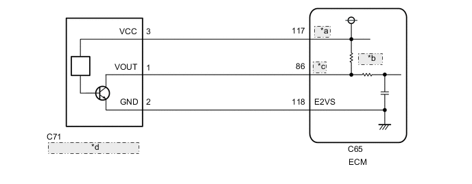
| *a | VCVS |
| *b | 1.5 kΩ |
| *c | VSM |
| *d | VALVEMATIC Shaft Sensor |
CAUTION / NOTICE / HINT
Tech Tips
Read Freeze Frame Data using the GTS. The ECM records vehicle and driving condition information as Freeze Frame Data the moment a DTC is stored. When troubleshooting, Freeze Frame Data can help determine if the vehicle was moving or stationary, if the engine was warmed up or not, if the air fuel ratio was lean or rich, and other data from the time the malfunction occurred.
PROCEDURE
-
READ OUTPUT DTC
-
Connect the GTS to the DLC3.
-
Turn the engine switch on (IG).
-
Turn the GTS on.
-
Enter the following menus: Powertrain / Engine and ECT / Trouble Codes.
Powertrain > Engine and ECT > Trouble Codes -
Read the DTCs.
Result Result Proceed to DTC P265B is output A DTC P265C or P265D is output B DTC P265B, P265C and/or P265D and other DTCs are output C Tech Tips
If any DTCs other than P265B, P265C and P265D are output, troubleshoot those DTCs first.
B 
CHECK HARNESS AND CONNECTOR Click here
C 
GO TO DTC CHART Click here
A 
-
-
CLEAR DTC
-
Connect the GTS to the DLC3.
-
Turn the engine switch on (IG).
-
Turn the GTS on.
-
Clear the DTCs.
Powertrain > Engine and ECT > Trouble Codes -
Turn the engine switch off and wait for at least 30 seconds.
Result Proceed to NEXT
NEXT
-
-
PERFORM SIMULATION TEST
-
Connect the GTS to the DLC3.
-
Turn the engine switch on (IG).
-
Turn the GTS on.
-
Start the engine and warm it up until the engine coolant temperature reaches 75°C (167°F) or higher.
-
Idle the engine for 30 seconds or more.
-
Increase the engine speed to 4000 rpm.
-
Enter the following menus: Powertrain / Engine and ECT / Trouble Codes.
Powertrain > Engine and ECT > Trouble Codes -
Read the DTCs.
Result Result Proceed to DTC P265B is output A DTCs are not output B
B
GO TO STEP 7 Click here
A
-
-
PERFORM ACTIVE TEST USING GTS (ACTIVATE THE VALVEMATIC (ENG ON))
-
Connect the GTS to the DLC3.
-
Start the engine and warm it up until the engine coolant temperature stabilizes. (Engine coolant temperature 40°C or higher)
-
Turn the engine switch off.
-
Restart the engine.
Tech Tips
Do not operate the accelerator pedal.
-
Turn the GTS on.
-
Enter the following menus: Powertrain / Engine and ECT / Active Test / Activate the VALVEMATIC(ENG ON) / Data List / MAP, VALVEMATIC Target Angle, VALVEMATIC Current Angle, VALVEMATIC bef Warm Up.
Powertrain > Engine and ECT > Active TestActive Test Display Activate the VALVEMATIC(ENG ON) Data List Display MAP VALVEMATIC Target Angle VALVEMATIC Current Angle VALVEMATIC bef Warm Up -
Check the Data List "VALVEMATIC bef Warm Up" display is "ON".
Tech Tips
If "VALVEMATIC bef Warm Up" is not "ON".
-
Restart the engine. (Do not operate the accelerator pedal.)
-
Perform the Active Test "Activate the VALVEMATIC before Warm Up" to set "VALVEMATIC bef Warm Up" to "ON". (Do not operate the accelerator pedal.)
-
-
Set the Active Test "Activate the VALVEMATIC(ENG ON)" to "High" and check that "VALVEMATIC Current Angle" follows "VALVEMATIC Target Angle" and the "MAP" value changes.
Standard GTS Operation Result High VALVEMATIC Current Angle: 260 deg(CA)
MAP: 25 to 40 kPa (188 to 300 mmHg)
-
Set the Active Test "Activate the VALVEMATIC(ENG ON)" to "OFF", and check that "VALVEMATIC bef Warm Up" returns to "ON".
-
Set the Active Test "Activate the VALVEMATIC(ENG ON)" to "Low" and check that "VALVEMATIC Current Angle" follows "VALVEMATIC Target Angle" and the "MAP" value changes.
Standard GTS Operation Result Low VALVEMATIC Current Angle: 106 deg(CA)
MAP: 35 to 65 kPa (263 to 488 mmHg)
OK When performing the Active Test, "VALVEMATIC Current Angle" follows "VALVEMATIC Target Angle" and the "MAP" value changes. Tech Tips
-
After the accelerator pedal is depressed and the Active Test operates once to "Low", "VALVEMATIC bef Warm Up" does not return to "ON". Therefore, in order to repeat the inspection, it is necessary to either perform the Active Test "Activate the VALVEMATIC before Warm Up" to set the VALVEMATIC system to the operating position that occurs before the engine is warmed up, or restart the engine.
-
When the vehicle is driven while there is a malfunction in the VALVEMATIC system and the valve lift amount is fixed at the minimum, the vehicle speed cannot exceed 30 to 60 km/h (19 to 37 mph).
-
If the intake valve advance angle is within the VALVEMATIC operation prohibition range depending on the operating state of the VVT system, the Active Test "Activate the VALVEMATIC(ENG ON)" is prohibited. If the advance angle cannot be detected due to a malfunction in the VVT system, the Active Test "Activate the VALVEMATIC(ENG ON)" is prohibited.
Result Proceed to OK NG -
NG
REPLACE CONTINUOUSLY VARIABLE VALVE LIFT CONTROLLER ASSEMBLY Click here
OK
-
-
INSPECT CAMSHAFT HOUSING SUB-ASSEMBLY
-
Inspect the shaft monitor target.
OK The shaft monitor target is free of foreign matter and installed correctly. Tech Tips
Perform "Inspection After Repair" after replacing the camshaft housing sub-assembly.
Result Proceed to OK NG
NG
REPLACE CAMSHAFT HOUSING SUB-ASSEMBLY Click here
OK
-
-
INSPECT VALVE LIFT CONTROL ACTUATOR CONNECTOR
-
Inspect the valve lift control actuator connector.
OK Valve lift control actuator connector is installed correctly. Tech Tips
Perform "Inspection After Repair" after replacing the continuously variable valve lift controller assembly.
Result Proceed to OK NG
NG
REPLACE CONTINUOUSLY VARIABLE VALVE LIFT CONTROLLER ASSEMBLY Click here
OK
-
-
CHECK HARNESS AND CONNECTOR
Tech Tips
Make sure that the connector is properly connected. If it is not, securely connect it and check for DTCs again.
-
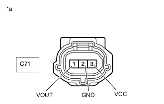
*a Front view of wire harness connector
(to VALVEMATIC shaft sensor)
Disconnect the VALVEMATIC shaft sensor connector.
-
Turn the engine switch on (IG).
-
Measure the voltage according to the value(s) in the table below.
Standard Voltage Tester Connection Condition Specified Condition C71-3 (VCC) - Body ground Engine switch on (IG) 4.5 to 5.5 V C71-1 (VOUT) - Body ground Engine switch on (IG) 3.0 to 5.5 V -
Turn the engine switch off and wait for at least 30 seconds.
-
Measure the resistance according to the value(s) in the table below.
Standard Resistance Tester Connection Condition Specified Condition C71-3 (VCC) - C71-1 (VOUT) Engine switch off 1.425 to 1.575 kΩ C71-2 (GND) - Body ground Always Below 1 Ω Result Proceed to OK NG
NG
CHECK HARNESS AND CONNECTOR (VALVEMATIC SHAFT SENSOR - ECM) Click here
OK
-
-
CHECK SENSOR INSTALLATION (VALVEMATIC SHAFT SENSOR)
-
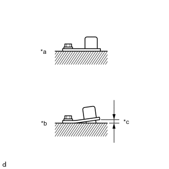
*a OK *b NG *c Clearance Check the VALVEMATIC shaft sensor installation condition.
OK VALVEMATIC shaft sensor is installed correctly. Result Proceed to OK NG
OK
REPLACE VALVEMATIC SHAFT SENSOR Click here
NG
SECURELY REINSTALL VALVEMATIC SHAFT SENSOR Click here
-
-
CHECK HARNESS AND CONNECTOR (VALVEMATIC SHAFT SENSOR - ECM)
-
Disconnect the VALVEMATIC shaft sensor connector.
-
Disconnect the ECM connector.
-
Measure the resistance according to the value(s) in the table below.
Standard Resistance Tester Connection Condition Specified Condition C71-3 (VCC) - C65-117 (VCVS) Always Below 1 Ω C71-1 (VOUT) - C65-86 (VSM) Always Below 1 Ω C71-2 (GND) - C65-118 (E2VS) Always Below 1 Ω C71-3 (VCC) or C65-117 (VCVS) - Body ground and other terminals Always 10 kΩ or higher C71-1 (VOUT) or C65-86 (VSM) - Body ground and other terminals Always 10 kΩ or higher C71-2 (GND) or C65-118 (E2VS) - Body ground and other terminals Always 10 kΩ or higher Result Proceed to OK NG
OK
REPLACE ECM Click here
NG
REPAIR OR REPLACE HARNESS OR CONNECTOR
-