CYLINDER HEAD GASKET REMOVAL
CAUTION / NOTICE / HINT
The camshaft housing sub-assembly is replaced with an assembled unit that includes the camshaft housing sub-assembly, camshafts, camshaft bearing caps, valve rocker shaft and valve rocker arm lost motion damper sub-assembly. If disassembled, replace the camshaft housing sub-assembly.
The camshafts cannot be replaced by themselves.
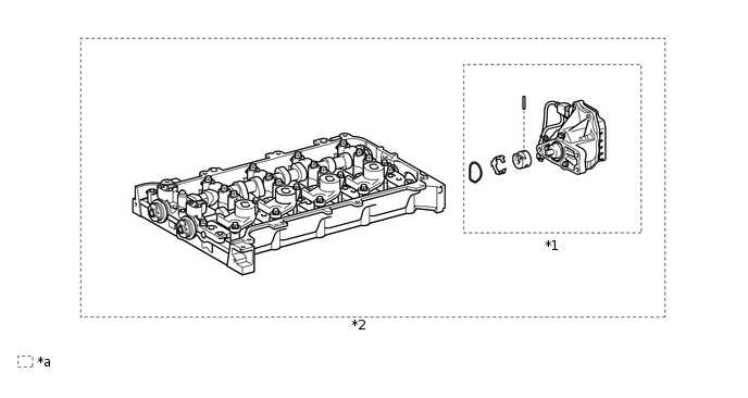
*1
Continuously Variable Valve Lift Controller Assembly
*2
Camshaft Housing Sub-assembly
*a
Set of parts that are replaced together
-
-
PROCEDURE
REMOVE CAMSHAFT HOUSING SUB-ASSEMBLY
REMOVE FUEL TUBE SUB-ASSEMBLY
REMOVE FUEL DELIVERY PIPE SUB-ASSEMBLY
REMOVE NO. 1 DELIVERY PIPE SPACER
REMOVE FUEL INJECTOR ASSEMBLY
REMOVE NO. 1 EXHAUST MANIFOLD HEAT INSULATOR
REMOVE MANIFOLD STAY
REMOVE EXHAUST MANIFOLD
REMOVE NO. 1 WATER BY-PASS PIPE
REMOVE NO. 1 VALVE ROCKER ARM SUB-ASSEMBLY
REMOVE VALVE LASH ADJUSTER ASSEMBLY
REMOVE VALVE STEM CAP
REMOVE CYLINDER HEAD SUB-ASSEMBLY
-
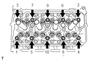
Using a 10 mm bi-hexagon wrench, uniformly loosen and remove the 10 cylinder head bolts and 10 plate washers in several steps in the sequence shown in the illustration.
Note:Removing the cylinder head set bolts in the wrong order may cause warpage or cracking of the cylinder head sub-assembly.
Do not drop the plate washers into the cylinder head sub-assembly.
Using a screwdriver remove the cylinder head sub-assembly by prying between the cylinder head sub-assembly and cylinder block sub-assembly, and remove the cylinder head sub-assembly.
Tip:Tape the screwdriver tip before use.
Note:Be careful not to damage the contact surfaces of the cylinder head sub-assembly and cylinder block sub-assembly.
-
REMOVE CYLINDER HEAD GASKET
-
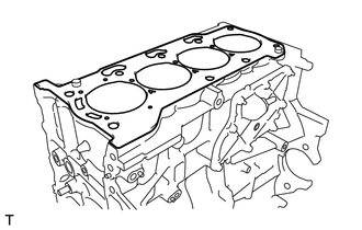
Remove the cylinder head gasket.
-