CLUTCH ACTUATOR(for C553A) REMOVAL
CAUTION / NOTICE / HINT
If reusing the clutch actuator assembly, make sure to perform the clutch position adjustment operation.
When installing a new clutch actuator assembly, it is not necessary to perform the clutch position adjustment operation.
PROCEDURE
CLUTCH POSITION ADJUSTMENT
Tip:The multi-mode manual transmission system has a load controlled clutch cover adjustment system. The pressure plate moves depending on the wear of the clutch disc lining.
When removing or installing any parts related to the multi-mode manual transmission system, move the clutch actuator to the clutch clamp position. This is for normal operation of the load controlled clutch cover (adjustment system).
If the clutch position adjustment operation input fails, perform the operation again from step (1) more than 15 seconds after turning the ignition switch off.
Note:Do not depress the brake pedal while performing the clamp position adjustment using GTS.
Perform clutch position adjustment.
Prepare the vehicle:
Stop the vehicle.
Move the shift lever to N.
Turn the ignition switch off.
Apply the parking brake.
Connect the GTS to the DLC3.
Turn the ignition switch to ON.
Turn the GTS on.
Enter the following menus: Powertrain / Multi-Mode M/T / Utility / Parts Exchange.
Powertrain > Multi-Mode M/T > Utility
Tester Display
Parts Exchange
Follow the instruction on the GTS.
Complete clutch position adjustment.
Turn the GTS off.
Turn the ignition switch off.
DISCONNECT CABLE FROM NEGATIVE BATTERY TERMINAL
Note:After turning the ignition switch off, waiting time may be required before disconnecting the cable from the negative (-) battery terminal. Therefore, make sure to read the disconnecting the cable from the negative (-) battery terminal notices before proceeding with work.
REMOVE BATTERY
REMOVE BATTERY CLAMP SUB-ASSEMBLY
REMOVE CLUTCH ACTUATOR ASSEMBLY
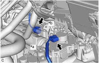
*a
Clutch Stroke Sensor Connector
*b
Clutch Motor Connector
Disconnect the clutch stroke sensor connector and clutch motor connector.
Note:Do not forcibly pull the connector as this may damage the wire harness.
-
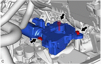
Remove the 3 bolts and clutch actuator assembly from the multi-mode manual transaxle assembly.
Note:Loosen the bolts slowly, and be careful not to get your fingers caught as the clutch actuator assembly moves due to the reaction force from the clutch cover assembly.
Do not drop the removed clutch actuator assembly or subject it to impacts.
REMOVE CLUTCH STROKE SENSOR
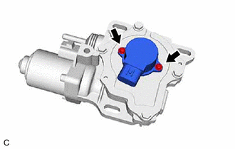
Remove the 2 screws and clutch stroke sensor from the clutch actuator assembly.
Remove the O-ring.