LANE DEPARTURE ALERT SYSTEM Main Switch Circuit
| DTC Code | DTC Name |
|---|---|
| Main Switch Circuit |
DESCRIPTION
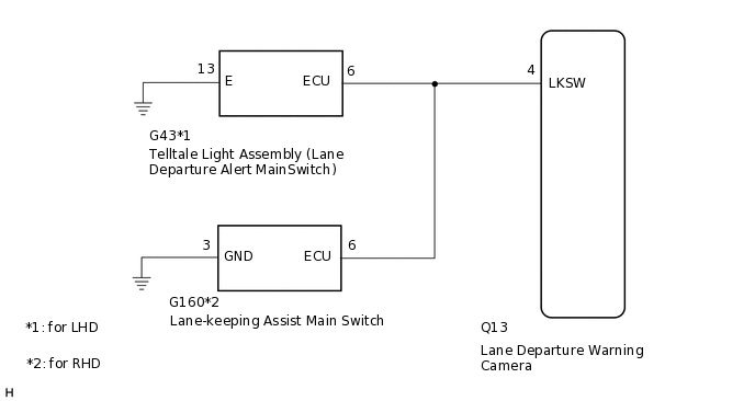
*1: for LHD
*2: for RHD
The lane departure warning camera receives a lane departure alert main switch*1 or lane-keeping assist main switch*2 signal from the telltale light assembly (lane departure alert main switch).
WIRING DIAGRAM
PROCEDURE
CHECK VEHICLE TYPE
Check vehicle type.
Result
Result
Proceed to
for LHD
A
for RHD
B
B CHECK HARNESS AND CONNECTOR (LANE-KEEPING ASSIST MAIN SWITCH - LANE DEPARTURE WARNING CAMERA AND BODY GROUND)Click here
CHECK HARNESS AND CONNECTOR (TELLTALE LIGHT ASSEMBLY [LANE DEPARTURE ALERT MAIN SWITCH] - LANE DEPARTURE WARNING CAMERA AND BODY GROUND)
Disconnect the G43 telltale light assembly (lane departure alert main switch) connector.
Disconnect the Q13 lane departure warning camera connector.
Measure the resistance according to the value(s) in the table below.
Standard Resistance
Tester Connection
Condition
Specified Condition
G43-6 (ECU) - Q13-4 (LKSW)
Always
Below 1 Ω
G43-6 (ECU) - Body ground
Always
10 kΩ or higher
G43-13 (E) - Body ground
Always
Below 1 Ω
Result
Proceed to
OK
NG
NG REPAIR OR REPLACE HARNESS OR CONNECTOR
INSPECT TELLTALE LIGHT ASSEMBLY
Remove the telltale light assembly.
Inspect the telltale light assembly.
Result
Proceed to
OK
NG
CHECK HARNESS AND CONNECTOR (LANE-KEEPING ASSIST MAIN SWITCH - LANE DEPARTURE WARNING CAMERA AND BODY GROUND)
Disconnect the G160 lane-keeping assist main switch connector.
Disconnect the Q13 lane departure warning camera connector.
Measure the resistance according to the value(s) in the table below.
Standard Resistance
Tester Connection
Condition
Specified Condition
G160-6 (ECU) - Q13-4 (LKSW)
Always
Below 1 Ω
G160-6 (ECU) - Body ground
Always
10 kΩ or higher
G160-3 (GND) - Body ground
Always
Below 1 Ω
Result
Proceed to
OK
NG
NG REPAIR OR REPLACE HARNESS OR CONNECTOR
INSPECT LANE-KEEPING ASSIST MAIN SWITCH
Remove the lane-keeping assist main switch.
Inspect the lane-keeping assist main switch.
Result
Proceed to
OK
NG