MULTI-MODE MANUAL TRANSAXLE UNIT REASSEMBLY
CAUTION / NOTICE / HINT
When replacing any tapered roller bearing outer race, replace both the tapered roller bearing and tapered roller bearing outer race with new ones.
PROCEDURE
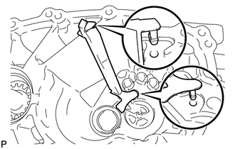
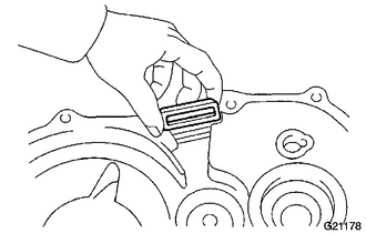
INSTALL OUTPUT SHAFT (MTM) COVER
-
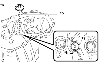
*a
Hole
*b
Protrusion
Install the output shaft (MTM) cover to the front transaxle case as shown in the illustration.
-
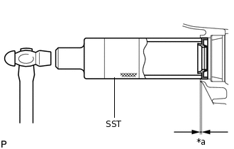
INSTALL FRONT OUTPUT SHAFT BEARING (OUTER RACE)
-
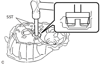
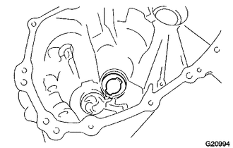
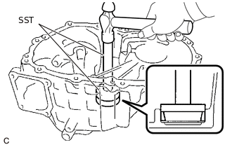
Using SST and a hammer, install the front output shaft bearing (outer race) to the front transaxle case.
09950-60010
09951-00510
09950-70010
09951-07200
Note:Do not damage or deform the front output shaft bearing (outer race).
-
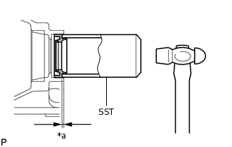
INSTALL FRONT DIFFERENTIAL CASE FRONT TAPERED ROLLER BEARING (OUTER RACE)
-
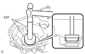
Using SST and a hammer, install the front differential case front tapered roller bearing (outer race) to the front transaxle case.
09950-60010
09951-00620
09950-70010
09951-07200
Note:Do not damage or deform the front differential case front tapered roller bearing (outer race).
-
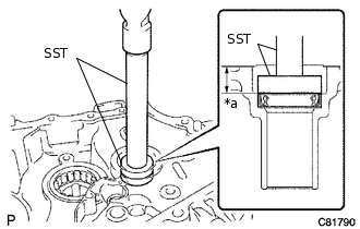
INSTALL FRONT DIFFERENTIAL CASE REAR TAPERED ROLLER BEARING (OUTER RACE)
Install the differential case shim to the manual transmission case.
Tip:When reusing the front differential case rear tapered roller bearing (outer race), reuse the original differential case shim.
When installing a new front differential case rear tapered roller bearing (outer race), first select and install a differential case shim which is thinner than the original.
-
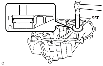
Using SST and a hammer, install the front differential case rear tapered roller bearing (outer race) to the manual transmission case.
09950-60020
09951-00710
09950-70010
09951-07200
Note:Do not damage or deform the front differential case rear tapered roller bearing (outer race).
ADJUST DIFFERENTIAL SIDE BEARING PRELOAD
Coat the front differential case front tapered roller bearing and front differential case rear tapered roller bearing with gear oil.
-
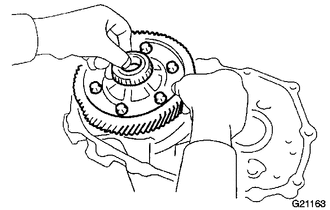
Install the front differential case to the front transaxle case.
-
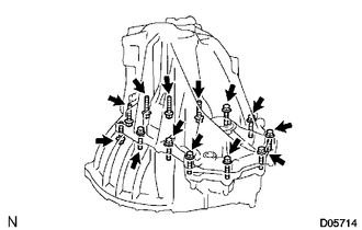
Install the manual transmission case with the 13 bolts.
29.4 N*m
300 kgf*cm
22 ft.*lbf
Tip:From manual transmission case side: 8 bolts
From front transaxle case side: 5 bolts
-
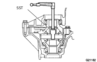
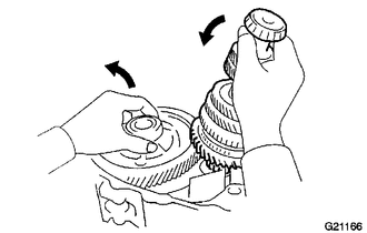
Using SST and a torque wrench, turn the front differential case clockwise and counterclockwise 2 or 3 times to allow the bearings to settle.
09564-32011
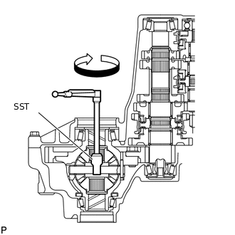
Using SST and a torque wrench, measure the starting preload.
09564-32011
Preload (at starting)
New Bearing
0.8 to 1.5 N*m (9 to 15 kgf*cm, 8 to 13 in.*lbf)
Used Bearing
0.5 to 0.9 N*m (6 to 9 kgf*cm, 5 to 7 in.*lbf)
If the result is not as specified, replace the differential case shim with one of a different thickness. Use the table below to select a differential case shim which will ensure that the preload is within the specified range.
Differential Case Shim Thickness
Part No.
Mark
Thickness
mm (in.)
Part No.
Mark
Thickness
mm (in.)
90564-41065
01
1.10 (0.0433)
90564-41075
11
1.60 (0.0630)
90564-41066
02
1.15 (0.0453)
90564-41076
12
1.65 (0.0650)
90564-41067
03
1.20 (0.0472)
90564-41077
13
1.70 (0.0669)
90564-41068
04
1.25 (0.0492)
90564-41078
14
1.75 (0.0689)
90564-41069
05
1.30 (0.0512)
90564-41079
15
1.80 (0.0709)
90564-41070
06
1.35 (0.0531)
90564-41080
16
1.85 (0.0728)
90564-41071
07
1.40 (0.0551)
90564-41081
17
1.90 (0.0748)
90564-41072
08
1.45 (0.0571)
90564-41082
18
1.95 (0.0768)
90564-41073
09
1.50 (0.0591)
90564-41083
19
2.00 (0.0787)
90564-41074
10
1.55 (0.0610)
-
-
-
Remove the 13 bolts and manual transmission case from the front transaxle case.
Tip:From manual transmission case side: 8 bolts
From front transaxle case side: 5 bolts
Remove the front differential case from the front transaxle case.
INSTALL REAR OUTPUT SHAFT BEARING SHIM
-
Install the rear output shaft bearing shim to the manual transmission case.
Tip:When reusing the rear output shaft bearing (outer race), reuse the original rear output shaft bearing shim.
When installing a new rear output shaft bearing (outer race), first select and install a rear output shaft bearing shim which is thinner than the original.
-
INSTALL REAR OUTPUT SHAFT BEARING (OUTER RACE)
-
Using SST and a hammer, install in the rear output shaft bearing (outer race) to the manual transmission case.
09950-60010
09951-00570
09950-70010
09951-07360
Note:Do not damage or deform the rear output shaft bearing (outer race).
-
ADJUST OUTPUT SHAFT BEARING PRELOAD
Coat the front differential case front tapered roller bearing, front differential case rear tapered roller bearing, front output shaft bearing and rear output shaft bearing with gear oil.
-
Install the front differential case to the front transaxle case.
-
Install the output shaft assembly and front differential case to the front transaxle case.
-
Install the manual transmission case to the front transaxle case with the 13 bolts.
29.4 N*m
300 kgf*cm
22 ft.*lbf
Tip:From manual transmission case side: 8 bolts
From front transaxle case side: 5 bolts
-
Using SST and a torque wrench, turn the front differential case and output shaft assembly clockwise and counterclockwise 2 or 3 times to allow the bearings to settle.
09564-32011
Using SST and a torque wrench, measure the starting preload. Calculate the rear output shaft bearing shim value using the following formula.
09564-32011
Formula
(Differential side bearing preload + Output shaft bearing preload) - Differential side bearing preload = Output shaft bearing preload
Preload (at starting)
New Bearing
3.4 to 6.7 N*m (35 to 68 kgf*cm, 31 to 59 in.*lbf)
Used Bearing
2.1 to 4.2 N*m (22 to 42 kgf*cm, 19 to 37 in.*lbf)
If the result is not as specified, replace the rear output shaft bearing shim with one of a different thickness. Use the table below to select a rear output shaft bearing shim which will ensure that the preload is within the specified range.
Rear Output Shaft Bearing Shim Thickness
Part No.
Mark
Thickness
mm (in.)
Part No.
Mark
Thickness
mm (in.)
90564-38001
A
1.55 (0.0610)
90564-38009
J
1.95 (0.0768)
90564-38002
B
1.60 (0.0630)
90564-38010
K
2.00 (0.0787)
90564-38003
C
1.65 (0.0650)
90564-38011
L
2.05 (0.0807)
90564-38004
D
1.70 (0.0669)
90564-38012
M
2.10 (0.0827)
90564-38005
E
1.75 (0.0689)
90564-38013
N
2.15 (0.0846)
90564-38006
F
1.80 (0.0709)
90564-38014
P
2.20 (0.0866)
90564-38007
G
1.85 (0.0728)
90564-38015
Q
2.25 (0.0886)
90564-38008
H
1.90 (0.0748)
-
-
-
Remove the 13 bolts and manual transmission case from the front transaxle case.
Tip:From manual transmission case side: 8 bolts
From front transaxle case side: 5 bolts
Remove the output shaft assembly from the front transaxle case.
Remove the front differential case from the front transaxle case.
INSTALL REAR INPUT SHAFT BEARING SHIM
-
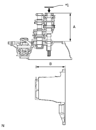
*1
Rear Input Shaft Bearing Shim
Using a vernier caliper, accurately measure the dimensions (A) and (B) shown in the illustration.
Select a rear input shaft bearing shim that brings the value within the specified range.
Standard
Shim thickness (B - A) should be more than 0 mm (0 in.) and less than 0.1 mm (0.00393 in.)
Rear Input Shaft Bearing Shim Thickness
Part No.
Mark
Thickness
mm (in.)
Part No.
Mark
Thickness
mm (in.)
90564-38006
F
1.80 (0.0709)
90564-38013
N
2.15 (0.0846)
90564-38007
G
1.85 (0.0728)
90564-38014
P
2.20 (0.0866)
90564-38008
H
1.90 (0.0748)
90564-38015
Q
2.25 (0.0886)
90564-38009
J
1.95 (0.0768)
90564-38016
R
2.30 (0.0906)
90564-38010
K
2.00 (0.0787)
90564-38017
S
2.35 (0.0925)
90564-38011
L
2.05 (0.0807)
90564-38018
T
2.40 (0.0945)
90564-38012
M
2.10 (0.0827)
-
-
-
Install the rear input shaft bearing shim to the manual transmission case.
-
INSTALL NO. 2 OIL RECEIVER PIPE (MTM)
-
Install No. 2 oil receiver pipe (MTM) to the manual transmission case.
Note:Do not damage No. 2 oil receiver pipe (MTM).
-
INSTALL FRONT DRIVE SHAFT OIL SEAL LH
Coat the lip of a new front drive shaft oil seal LH with MP grease.
-
*a
Depth
Using SST and a hammer, install the front drive shaft oil seal LH to the manual transmission case.
09316-60011
09316-00011
Standard Depth
2.1 to 3.1 mm (0.0827 to 0.122 in.)
Note:Be careful not to damage the lip of the front drive shaft oil seal LH.
INSTALL FRONT DRIVE SHAFT OIL SEAL RH
Coat the lip of a new front drive shaft oil seal RH with MP grease.
-
*a
Depth
Using SST and a hammer, install the front drive shaft oil seal RH to the front transaxle case.
09636-20010
Standard Depth
1.7 to 2.7 mm (0.0670 to 0.106 in.)
Note:Be careful not to damage the lip of the front drive shaft oil seal RH.
INSTALL FRONT TRANSAXLE CASE OIL SEAL
Coat the lip of a new front transaxle case oil seal with MP grease.
-
*a
Depth
Using SST and a hammer, install the front transaxle case oil seal to the front transaxle case.
09950-60010
09951-00360
09950-70010
09951-07150
Standard Depth
14.4 to 15.4 mm (0.567 to 0.606 in.)
INSTALL TRANSMISSION MAGNET
-
Clean the transmission magnet and then install it to the front transaxle case.
-
INSTALL FRONT DIFFERENTIAL CASE
-
Coat the front differential case front tapered roller bearing and front differential case rear tapered roller bearing with gear oil.
Install the front differential case to the front transaxle case.
-
INSTALL OUTPUT SHAFT ASSEMBLY
-
Install the output shaft assembly to the front transaxle case.
-
INSTALL INPUT SHAFT ASSEMBLY
-
Coat the sliding and rotating surfaces of the input shaft assembly and output shaft assembly with gear oil, and install them to the front transaxle case.
-
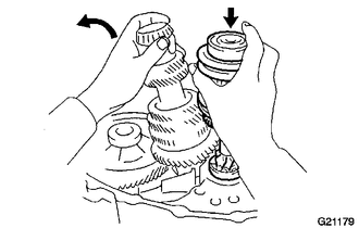
INSTALL NO. 2 GEAR SHIFT FORK SHAFT
-
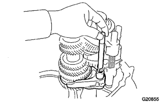
Install the No. 2 gear shift fork to the No. 2 gear shift fork shaft.
Using a plastic hammer, install a new snap ring to the No. 2 gear shift fork shaft.
Tip:Use a piece of cloth to keep the snap ring from flying off.
Install the reverse shift fork to the No. 2 gear shift fork shaft.
-
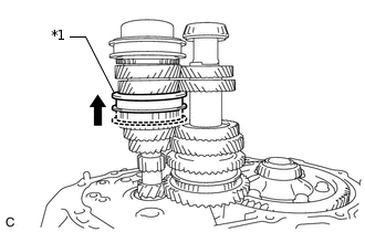
*1
No. 2 Transmission Hub Sleeve
Shift the No. 2 transmission hub sleeve to the 4th gear position.
-
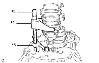
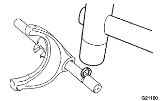
*1
No. 2 Gear Shift Fork Shaft
*2
No. 2 Gear Shift Fork
*3
Reverse Shift Fork
Install the No. 2 gear shift fork shaft, No. 2 gear shift fork and reverse shift fork to the front transaxle case.
-
Install a new bolt to the No. 2 gear shift fork.
15.7 N*m
160 kgf*cm
12 ft.*lbf
-
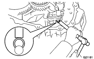
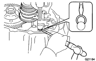
Using a brass bar and a hammer, install a new snap ring to the No. 2 gear shift fork shaft.
Tip:Use a piece of cloth to keep the snap ring from flying off.
-
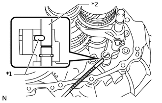
*1
Straight Pin
*2
No. 2 Gear Shift Fork Shaft
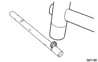
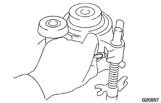
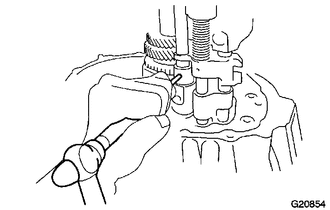
Using a Magnet Hand, install the straight pin to the reverse shift fork.
Note:Insert the straight pin along the groove on the No. 2 gear shift fork shaft as shown in the illustration.
-
INSTALL NO. 3 GEAR SHIFT FORK SHAFT
-
Using a plastic hammer, install a new snap ring to the No. 3 gear shift fork shaft.
Tip:Use a piece of cloth to keep the snap ring from flying off.
-
Install the No. 3 gear shift fork to the No. 3 transmission hub sleeve.
-
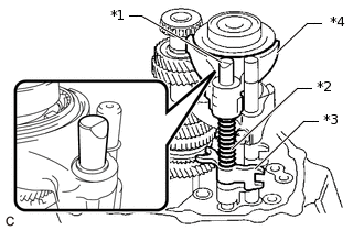
*1
No. 3 Gear Shift Fork Shaft
*2
Compression Spring
*3
No. 3 Gear Shift Head
*4
No. 3 Gear Shift Fork
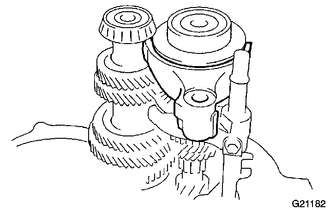
Pass the No. 3 gear shift fork shaft through the No. 3 gear shift fork, compression spring and No. 3 gear shift head, and then install them to the front transaxle case.
-
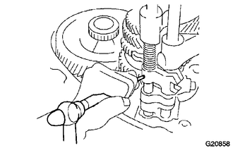
Using a 5 mm pin punch and a hammer, install the slotted spring pin to the No. 3 gear shift head to secure the No. 3 gear shift head to the No. 3 gear shift fork shaft.
-
Using a screwdriver and hammer, install a new snap ring to the No. 3 gear shift fork shaft.
Tip:Use a piece of cloth to keep the snap ring from flying off.
-
Install the straight pin to the No. 3 gear shift fork.
-
INSTALL NO. 1 GEAR SHIFT FORK SHAFT
-
Using a plastic hammer, install a new snap ring to the No. 1 gear shift fork shaft.
Tip:Use a piece of cloth to keep the snap ring from flying off.
-
Install the No. 1 gear shift fork to the reverse gear.
-
Pass the No. 1 gear shift fork shaft through the No. 1 gear shift head and No. 1 gear shift fork, and then install them to the front transaxle case.
-
Using a 5 mm pin punch and a hammer, install the slotted spring pin to the No. 1 gear shift head to secure the No. 1 gear shift head to the No. 1 gear shift fork shaft.
-
Install a new bolt to No. 1 gear shift fork.
15.7 N*m
160 kgf*cm
12 ft.*lbf
-
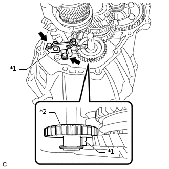
INSTALL REVERSE IDLER GEAR SUB-ASSEMBLY
-
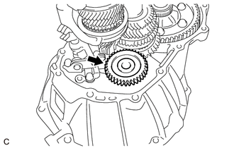
Install the reverse idler gear sub-assembly to the front transaxle case.
-
INSTALL REVERSE IDLER GEAR SHAFT
Coat the reverse idler gear shaft and reverse idler gear sub-assembly with gear oil.
Pass the reverse idler gear shaft through the reverse idler gear sub-assembly, and then install it to the front transaxle case.
-
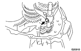
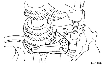
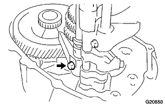
*a
Mark
Align the mark on the reverse idler gear shaft with the bolt hole, as shown in the illustration.
INSTALL REVERSE SHIFT ARM BRACKET ASSEMBLY
-
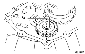
*1
Reverse Shift Arm Bracket Assembly
*2
Reverse Idler Gear Sub-assembly
Install the reverse shift arm bracket assembly to the front transaxle case with the 2 bolts.
17.2 N*m
175 kgf*cm
13 ft.*lbf
Note:Set the top of the reverse shift arm bracket assembly into the groove on the reverse idler gear sub-assembly.
-
INSTALL MANUAL TRANSMISSION CASE
Remove any remaining seal packing (FIPG) from the contact surfaces of the manual transmission case and front transaxle case.
Note:Make sure that there is no gear oil on the contact surfaces.
-
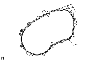
*a
FIPG
Seal Diameter 1.2 mm (0.0472 in.)
Apply seal packing (FIPG) to the manual transmission case.
Seal Packing
Toyota Genuine Seal Packing 1281, Three Bond 1281 or equivalent
Note:Install the parts within 10 minutes of application. Otherwise, the seal packing (FIPG) must be removed and reapplied.
Apply seal packing (FIPG) in a continuous line (width 1.2 mm (0.0472 in.)) to the sealing surface of the manual transmission case.
Install the manual transmission case to the front transaxle case.
-
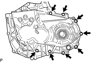
Install the 8 bolts to the manual transmission case side.
29.4 N*m
300 kgf*cm
22 ft.*lbf
-
Install the 5 bolts to the front transaxle case side.
29.4 N*m
300 kgf*cm
22 ft.*lbf
INSTALL REVERSE IDLER GEAR SHAFT BOLT
Clean and degrease the reverse idler gear shaft bolt and installation hole in the manual transmission case.
-
*a
Adhesive
Apply adhesive to the reverse idler gear shaft bolt threads.
Adhesive
Toyota Genuine Adhesive 1324, Three Bond 1324 or equivalent
Note:In order to ensure proper installation of the reverse idler gear shaft bolt, apply adhesive to the reverse idler gear shaft bolt and install it within 10 minutes of adhesive application.
-
Install the reverse idler gear shaft bolt and a new gasket to the manual transmission case.
29.4 N*m
300 kgf*cm
22 ft.*lbf
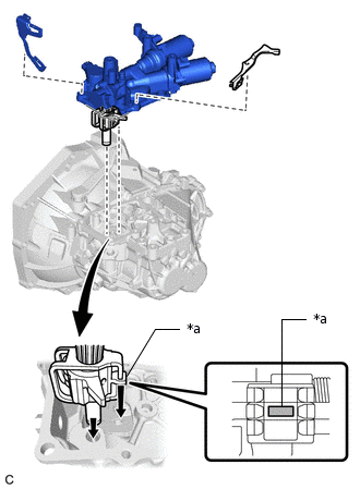
INSTALL SHIFT AND SELECT ACTUATOR ASSEMBLY
Clean the contact surfaces of the shift and select actuator assembly and manual transmission case with a non-residue solvent.
-
*a
FIPG
Seal Diameter 1.2 mm (0.0472 in.)
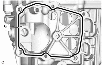
Apply FIPG in a continuous line to the shift and select actuator assembly as shown in the illustration.
FIPG
Toyota Genuine Seal Packing 1281, Three Bond 1281 or equivalent.
Note:Remove any oil from the contact surfaces.
Install the parts within 10 minutes of application. Otherwise, the seal packing (FIPG) must be removed and reapplied.
-
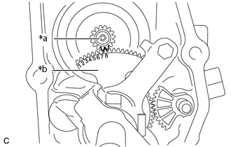
*a
Ring Gear
*b
Lever To Rotate Shift And Select Lever Shaft
Make sure that the 8th tooth from the left of the lever to rotate the shift and select lever shaft is meshed with the tooth groove of the ring gear as shown in the illustration.
-
*a
Inner No. 1 Shift Lever
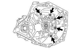
Install the shift and select actuator assembly and 2 wire harness clamp brackets to the multi-mode manual transaxle assembly with the 6 bolts.
18 N*m
184 kgf*cm
13 ft.*lbf
Note:Make sure that the shift fork shaft lever is in the neutral position when installing the shift and select actuator assembly, otherwise the shift and select actuator assembly, No. 1 gear shift head, No. 2 gear shift fork shaft or No. 3 gear shift head may be deformed.
INSTALL TRANSMISSION REVOLUTION SENSOR
-
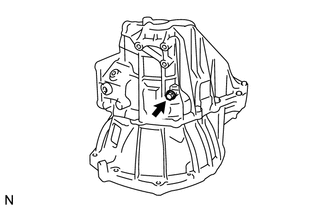
Install the transmission revolution sensor to the manual transmission case with the bolt.
7.8 N*m
80 kgf*cm
69 in.*lbf
Clean and degrease the bolt and installation hole in the manual transmission case.
-
*a
Adhesive
Apply adhesive to the bolt.
Adhesive
Toyota Genuine Adhesive 1344, Three Bond 1344 or equivalent
Note:In order to ensure proper installation of the bolt, apply adhesive to the bolt and install it within 10 minutes of adhesive application.
-
Install the transmission case protector to the manual transmission case with the bolt.
18.1 N*m
185 kgf*cm
13 ft.*lbf
-
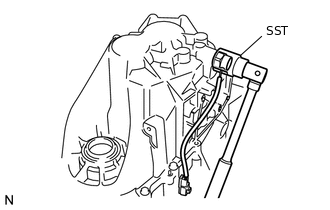
INSTALL PARK/NEUTRAL POSITION SWITCH ASSEMBLY
-
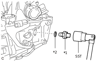
*1
Park/Neutral Position Switch Assembly
*2
Gasket
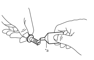
Using SST, remove the park/neutral position switch assembly and gasket from the manual transmission case.
09817-16011
39.2 N*m
400 kgf*cm
29 ft.*lbf
-
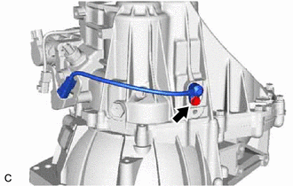
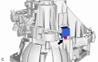
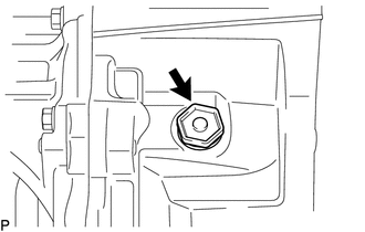
INSTALL NO. 1 LOCK BALL ASSEMBLY
Clean and degrease the No. 1 lock ball assembly and installation hole in the manual transmission case.
-
*a
Adhesive
Apply adhesive to the No. 1 lock ball assembly threads.
Adhesive
Toyota Genuine Adhesive 1324, Three Bond 1324 or equivalent
Note:In order to ensure proper installation of the No. 1 lock ball assembly, apply adhesive to the No. 1 lock ball assembly and install it within 10 minutes of adhesive application.
-
Using a 18 mm socket wrench, install the No. 1 lock ball assembly to the manual transmission case.
36.8 N*m
375 kgf*cm
27 ft.*lbf
Note:Do not install the No. 1 lock ball assembly with a gasket. Apply adhesive to the No. 1 lock ball assembly and install it.
If the No. 1 lock ball assembly is installed with a gasket, the transaxle may jump out of gear.
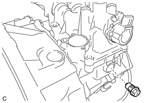
INSTALL BACK-UP LIGHT SWITCH ASSEMBLY
-
Using SST, remove the back-up light switch assembly and a new gasket from the manual transmission case.
09817-16011
40.2 N*m
410 kgf*cm
30 ft.*lbf
-
INSTALL FILLER PLUG
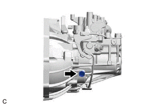
Install the filler plug and a new gasket to the manual transmission case.
39.2 N*m
400 kgf*cm
29 ft.*lbf
INSTALL DRAIN PLUG
-
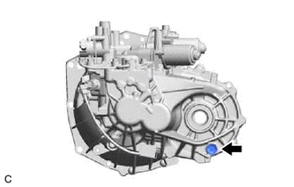
Install the drain plug and to a new gasket the manual transmission case.
39.2 N*m
400 kgf*cm
29 ft.*lbf
-
INSTALL MANUAL TRANSAXLE CASE PLUG
-
Install the manual transaxle case plug and a new gasket to the front transaxle case.
39.2 N*m
400 kgf*cm
29 ft.*lbf
-
INSTALL NO. 1 CLUTCH HOUSING COVER
INSTALL CLUTCH RELEASE FORK LEVER SHAFT OIL SEAL
INSTALL CLUTCH RELEASE FORK LEVER
INSTALL CLUTCH RELEASE BEARING ASSEMBLY