LIN COMMUNICATION SYSTEM TERMINALS OF ECU
CHECK CERTIFICATION ECU (SMART KEY ECU ASSEMBLY)
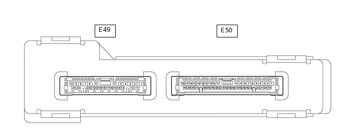
Disconnect the E49 certification ECU (smart key ECU assembly) connector.
Measure the resistance and voltage according to the value(s) in the table below.
Tip:Measure the values on the wire harness side with the connector disconnected.
Terminal No. (Symbol)
Wiring Color
Terminal Description
Condition
Specified Condition
E49-10 (E) - Body ground
BR - Body ground
Ground
Always
Below 1 Ω
E49-1 (+B) - Body ground
B - Body ground
+B power supply
Always
11 to 14 V
Reconnect the E49 certification ECU (smart key ECU assembly) connector.
Check for pulses according to the value(s) in the table below.
Terminal No. (Symbol)
Wiring Color
Terminal Description
Condition
Specified Condition
E49-5 (LIN) - Body ground
BE - Body ground
LIN communication line
Engine switch on (IG)
Pulse generation
CHECK STEERING LOCK ECU (STEERING LOCK ACTUATOR ASSEMBLY)

Disconnect the E47 steering lock ECU (steering lock actuator assembly) connector.
Measure the resistance and voltage according to the value(s) in the table below.
Tip:Measure the values on the wire harness side with the connector disconnected.
Terminal No. (Symbol)
Wiring Color
Terminal Description
Condition
Specified Condition
E47-1 (GND) - Body ground
W-B Body ground
Ground
Always
Below 1 Ω
E47-7 (B) - Body ground
V - Body ground
Battery power supply
Always
11 to 14 V
Reconnect the E47 steering lock ECU (steering lock actuator assembly) connector.
Check for pulses according to the value(s) in the table below.
Terminal No. (Symbol)
Wiring Color
Terminal Description
Condition
Specified Condition
E47-5 (LIN) - Body ground
BE - Body ground
LIN communication line
Engine switch on (IG)
Pulse generation
CHECK ID CODE BOX (IMMOBILISER CODE ECU) (for RHD)

Disconnect the E48 ID code box (immobiliser code ECU) connector.
Measure the resistance and voltage according to the value(s) in the table below.
Tip:Measure the values on the wire harness side with the connector disconnected.
Terminal No. (Symbol)
Wiring Color
Terminal Description
Condition
Specified Condition
E48-5 (GND) - Body ground
W-B - Body ground
Ground
Always
Below 1 Ω
E48-1 (+B) - Body ground
R - Body ground
+B power supply
Always
11 to 14 V
Reconnect the E48 ID code box (immobiliser code ECU) connector.
Check for pulses according to the value(s) in the table below.
Terminal No. (Symbol)
Wiring Color
Terminal Description
Condition
Specified Condition
E48-2 (LIN1) - Body ground
BE - Body ground
LIN communication line
Engine switch on (IG)
Pulse generation