ENGINE IMMOBILISER SYSTEM(w/ Entry and Start System) TERMINALS OF ECU
CHECK ENGINE SWITCH

Disconnect the H53 switch connector.
Measure the resistance according to the value(s) in the table below.
Terminal No. (Symbol)
Wiring Color
Terminal Description
Condition
Specified Condition
H53-8 (AGND) - Body ground
BR - Body ground
Ground
Always
Below 1 Ω
H53-5 (GND) - Body ground
W-B - Body ground
Ground
Always
Below 1 Ω
If the result is not as specified, there may be a malfunction on the wire harness side.
Reconnect the H53 switch connector.
Measure the voltage according to the value(s) in the table below.
Terminal No. (Symbol)
Wiring Color
Terminal Description
Condition
Specified Condition
H53-9 (TXCT) - H53-8 (AGND)
B - BR
Key code output signal
Engine switch off, 30 seconds or more after door opened or closed, and brake pedal*1 or clutch pedal*2 not depressed
Below 1 V
H53-9 (TXCT) - H53-8 (AGND)
B - BR
Key code output signal
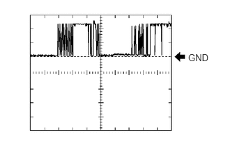
Engine switch off, key not in cabin, and 30 seconds or less after engine switch pushed
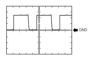
Pulse generation
(see waveform 1)
H53-10 (CODE) - H53-8 (AGND)
P - BR
Demodulated signal of key code data
Engine switch off, 30 seconds or more after door opened or closed, and brake pedal*1 or clutch pedal*2 not depressed
Below 1 V
H53-10 (CODE) - H53-8 (AGND)
P - BR
Demodulated signal of key code data
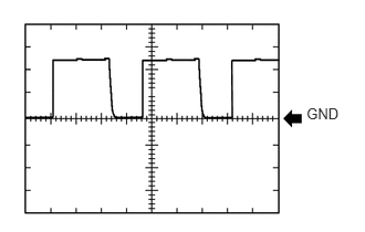
Engine switch off, key held against the engine switch and engine switch pushed*3
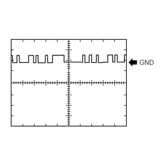
Pulse generation
(see waveform 2)
H53-11 (SWIL) - H53-5 (GND)
BE - W-B
Illumination signal
Light control switch off → tail
Below 2 V → 9 to 14 V
H53-14 (VC5) - H53-8 (AGND)
SB - BR
Power supply
Engine switch off, 30 seconds or more after door opened or closed, and brake pedal*1 or clutch pedal*2 not depressed
Below 1 V
H53-14 (VC5) - H53-8 (AGND)
SB - BR
Power supply
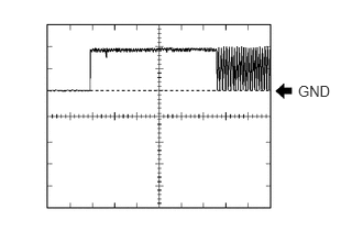
Engine switch off, key not in cabin, and 30 seconds or less after engine switch pushed
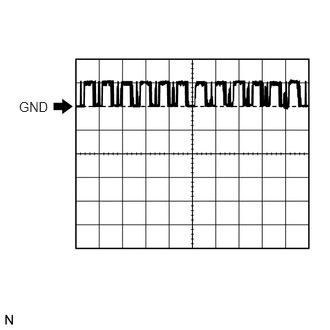
Pulse generation
(see waveform 3)
*1: except Manual Transaxle
*2: for Manual Transaxle
Tip:*3: Remove the key battery before performing this inspection.
If the result is not as specified, the engine switch may have a malfunction.
Inspect using an oscilloscope.
-

Waveform 1 (Reference)
Table 1. Measurement Condition Item
Content
Tester Connection
H53-9 (TXCT) - H53-8 (AGND)
Tool Setting
2 V/DIV., 20 ms./DIV.
Condition
Engine switch off, key not in cabin, and 30 seconds or less after engine switch pushed
-
Waveform 2 (Reference)
Table 2. Measurement Condition Item
Content
Tester Connection
H53-10 (CODE) - H53-8 (AGND)
Tool Setting
2 V/DIV., 20 ms./DIV.
Condition
Engine switch off, key held against engine switch and engine switch pushed*
Tip:*: Remove the key battery before performing this inspection.
-
Waveform 3 (Reference)
Table 3. Measurement Condition Item
Content
Tester Connection
H53-14 (VC5) - H53-8 (AGND)
Tool Setting
2 V/DIV., 20 ms./DIV.
Condition
Engine switch off, key not in cabin, and 30 seconds or less after engine switch pushed
-
CHECK CERTIFICATION ECU
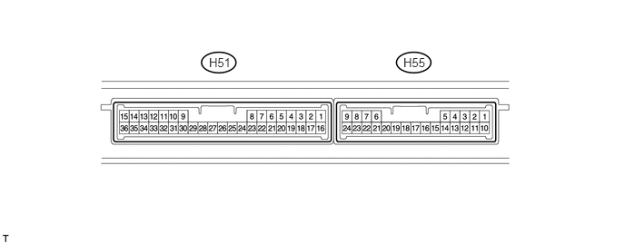
Disconnect the H51 ECU connector.
Measure the resistance and voltage according to the value(s) in the table below.
Terminal No. (Symbol)
Wiring Color
Terminal Description
Condition
Specified Condition
H51-1 (+B) - H51-15 (E)
W - W-B
+B power supply
Always
11 to 14 V
H51-17 (CUTB) - H51-15 (E)
W - W-B
+B power supply
Always
11 to 14 V
H51-16 (IG) - H51-15 (E)
L - W-B
Ignition power supply
Engine switch off → on (IG)
Below 1 V → 11 to 14 V
H51-15 (E) - Body ground
W-B - Body ground
Ground
Always
Below 1 Ω
If the result is not as specified, there may be a malfunction on the wire harness side.
Reconnect the H51 ECU connector.
Measure the resistance and voltage according to the value(s) in the table below.
Terminal No. (Symbol)
Wiring Color
Terminal Description
Condition
Specified Condition
H51-2 (IND) - H51-15 (E)
Y - W-B
Security indicator output
Engine switch off → on (IG)
Pulse generation
→ Below 2 V
H51-11 (SWIL) - H51-36 (AGND)
BE - BR
Illumination signal
Light control switch off
Below 2 V
H51-11 (SWIL) - H51-36 (AGND)
BE - BR
Illumination signal
Light control switch tail
9 to 14 V
H51-12 (TXCT) - H51-36 (AGND)
L - BR
Engine switch TXCT output
Engine switch off, 30 seconds or more after door opened or closed, and brake pedal*1 or clutch pedal*2 not depressed
Below 1 V
H51-12 (TXCT) - H51-36 (AGND)
L - BR
Engine switch TXCT output
Engine switch off, key not in cabin, and 30 seconds or less after engine switch pushed
Pulse generation
(see waveform 1)
H51-13 (CODE) - H51-36 (AGND)
P - BR
Engine switch CODE input
Key not in cabin
Below 1 V
H51-13 (CODE) - H51-36 (AGND)
P - BR
Engine switch CODE input
Engine switch off, key held against engine switch and engine switch pushed*3
Pulse generation
(see waveform 2)
H51-28 (VC5) - H51-36 (AGND)
SB - BR
Engine switch power supply
Engine switch off, 30 seconds or more after door opened or closed, and brake pedal*1 or clutch pedal*2 not depressed
Below 1 V
H51-28 (VC5) - H51-36 (AGND)
SB - BR
Engine switch power supply
Engine switch off, key not in cabin, and 30 seconds or less after engine switch pushed
Pulse generation
(see waveform 3)
H51-36 (AGND) - Body ground
BR - Body ground
Engine switch ground
Always
Below 1 Ω
*1: except Manual Transaxle
*2: for Manual Transaxle
Tip:*3: Remove the key battery before performing this inspection.
If the result is not as specified, the certification ECU may have a malfunction.
Inspect using an oscilloscope.
-
Waveform 1 (Reference)
Table 4. Measurement Condition Item
Content
Tester Connection
H51-12 (TXCT) - H51-36 (AGND)
Tool Setting
2 V/DIV., 20 ms./DIV.
Condition
Engine switch off, key not in cabin, and 30 seconds or less after engine switch pushed
-

Waveform 2 (Reference)
Table 5. Measurement Condition Item
Content
Tester Connection
H51-13 (CODE) - H51-36 (AGND)
Tool Setting
2 V/DIV., 20 ms./DIV.
Condition
Engine switch off, key held against engine switch and engine switch pushed*
Tip:*: Remove the key battery before performing this inspection.
-
Waveform 3 (Reference)
Table 6. Measurement Condition Item
Content
Tester Connection
H51-28 (VC5) - H51-36 (AGND)
Tool Setting
2 V/DIV., 20 ms./DIV.
Condition
Engine switch off, key not in cabin, and 30 seconds or less after engine switch pushed
-
CHECK ID CODE BOX

Disconnect the H111 box connector.
Measure the resistance and voltage according to the value(s) in the table below.
Terminal No. (Symbol)
Wiring Color
Terminal Description
Condition
Specified Condition
H111-1 (+B) - H111-8 (GND)
W - BR
+B power supply
Always
11 to 14 V
H111-8 (GND) - Body ground
BR - Body ground
Ground
Always
Below 1 Ω
If the result is not as specified, there may be a malfunction on the wire harness side.
Reconnect the H111 box connector.
Measure the voltage according to the value(s) in the table below.
Terminal No. (Symbol)
Wiring Color
Terminal Description
Condition
Specified Condition
H111-5 (EFII) - H111-8 (GND)
LG - BR
ECM input signal
3 seconds or less after initial combustion, or 3 seconds or less after engine switch turned on (IG) for the first time after battery reconnected
11 to 14 V → Pulse generation
(see waveform 1)
H111-6 (EFIO) - H111-8 (GND)
P - BR
ECM output signal
Engine switch off → on (IG)
11 to 14 V → Pulse generation
(see waveform 2)
If the result is not as specified, the ID code box may have a malfunction.
Inspect using an oscilloscope.
-
Waveform 1 (Reference)
Table 7. Measurement Condition Item
Content
Tester Connection
H111-5 (EFII) - H111-8 (GND)
Tool Setting
10 V/DIV., 100 ms./DIV.
Condition
3 seconds or less after initial combustion, or 3 seconds or less after engine switch turned on (IG) for the first time after battery reconnected
-
Waveform 2 (Reference)
Table 8. Measurement Condition Item
Content
Tester Connection
H111-6 (EFIO) - H111-8 (GND)
Tool Setting
10 V/DIV., 100 ms./DIV.
Condition
Engine switch on (IG)
-
CHECK STEERING LOCK ACTUATOR ASSEMBLY (STEERING LOCK ECU)
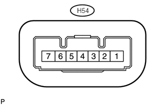
Disconnect the H54 ECU connector.
Measure the voltage and resistance according to the value(s) in the table below.
Terminal No. (Symbol)
Wiring Color
Terminal Description
Condition
Specified Condition
H54-1 (GND) - Body ground
W-B - Body ground
Ground
Always
Below 1 Ω
H54-6 (IG2) - H54-1 (GND)
B - W-B
IG2 signal input
Engine switch off → on (IG)
Below 1 V → 11 to 14 V
H54-7 (B) - Body ground
L - Body ground
Power source
Always
11 to 14 V
If the result is not as specified, there may be a malfunction on the wire harness side.
CHECK POWER MANAGEMENT CONTROL ECU
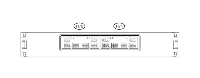
Disconnect the H71 ECU connector.
Measure the voltage and resistance according to the value(s) in the table below.
Terminal No. (Symbol)
Wiring Color
Terminal Description
Condition
Specified Condition
H71-1 (AM22) - Body ground
L - Body ground
Battery power
Always
11 to 14 V
H71-2 (AM21) - Body ground
B - Body ground
Battery power
Always
11 to 14 V
H71-5 (GND2) - Body ground
W-B - Body ground
Ground
Always
Below 1 Ω
H71-6 (GND) - Body ground
W-B - Body ground
Ground
Always
Below 1 Ω
If the result is not as specified, there may be a malfunction on the wire harness side.