AIR CONDITIONING SYSTEM (for Cold Area) TERMINALS OF ECU
-
CHECK AIR CONDITIONING AMPLIFIER ASSEMBLY (w/ HOT GAS HEATER)
-
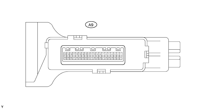
Disconnect the A9 air conditioning amplifier connector.
-
Measure the voltage and resistance of the wire harness side connector.
Symbols (Terminal No.) Wiring Color Terminal Description Condition Specified Condition +B (A9-40) - GND (A9-29) L-Y - L For memory backup Always 10 to 14 V IG+ (A9-20) - GND (A9-29) R-L - L Power source (IG) Ignition switch OFF Below 1 V IG+ (A9-20) - GND (A9-29) R-L - L Power source (IG) Ignition switch ON 10 to 14 V GND (A9-29) - Body ground L - Body ground Ground Always Below 1 Ω ACON (A9-8) - GND (A9-29) R-G - L A/C switch signal A/C switch OFF Below 1 V ACON (A9-8) - GND (A9-29) R-G - L A/C switch signal Ignition switch START
Blower switch ON
A/C switch ON
10 to 14 V IND- (A9-9) - GND (A9-29) R-L - L A/C indicator light signal A/C switch OFF Below 1 V IND- (A9-9) - GND (A9-29) R-L - L A/C indicator light signal Ignition switch START
Blower switch ON
A/C switch ON
10 to 14 V BLW (A9-38) - GND (A9-29) R-L - L Max HOT switch signal Temperature control knob: Max HOT Below 1 Ω BLW (A9-38) - GND (A9-29) R-L - L Max HOT switch signal Temperature control knob: Max HOT 10k Ω or higher HEAT (A9-5) - GND (A9-29) L-O - L Heater switch signal Heater switch ON Below 1 Ω HEAT (A9-5) - GND (A9-29) L-O - L Heater switch signal Heater switch OFF 10k Ω or higher MGC (A9-19) - GND (A9-29) B - L Magnet clutch relay signal Ignition switch START
Blower switch ON
10 to 14 V MGC (A9-19) - GND (A9-29) B - L Magnet clutch relay signal Ignition switch START
Blower switch OFF
Below 1 V TAIL (A9-7) - GND (A9-29) G - L Light control switch signal Light control switch ON 10 to 14 V TAIL (A9-7) - GND (A9-29) G - L Light control switch signal Light control switch OFF Below 1 V
-
If the result is not as specified, there may be a malfunction on the wire harness side.
-
-
Reconnect the A9 connector.
-
Measure the voltage and resistance of the connector.
Symbols (Terminal NO.) Wiring Color Terminal Description Condition Specified Condition S5 (A9-13) - SG-3 (A9-12) R-B - BR-Y Power supply for pressure sensor Ignition switch ON 4.5 to 5.5 V PRE (A9-4) - SG-3 (A9-12) BR - BR-Y Air conditioner pressure switch signal Ignition switch START
Refrigerant pressure normal: 0.18 MPa (1.9 kgf/cm2, 26 psi) to 3.03 MPa (31.0 kgf/cm2, 440 psi)
Blower switch ON
A/C switch ON
0.74 to 4.66 V PRE (A9-4) - SG-3 (A9-12) BR - BR-Y Air conditioner pressure switch signal Ignition switch START
Blower switch ON
A/C switch ON
Refrigerant pressure abnormal: pressure less than 0.18 MPa (1.9 kgf/cm2, 26 psi)
Below 0.74 V PRE (A9-4) - SG-3 (A9-12) BR - BR-Y Air conditioner pressure switch signal Ignition switch START
Blower switch ON
A/C switch ON
Refrigerant pressure abnormal: pressure more than 3.03 MPa (31.0 kgf/cm2, 440 psi)
Above 4.66 V TAM (A9-25) - SG-3 (A9-12) W-G - BR-Y Ambient temperature sensor signal Ignition switch ON
Ambient temperature is 25 °C (77°F)
1.35 to 1.75 V SG-3 (A9-12) - Body ground BR-Y - Body ground Ground for Ambient temperature sensor and pressure sensor Always Below 1 Ω MGC (A9-19) - GND (A9-29) B - L Magnet clutch signal Ignition switch START
Magnet clutch is engaged
10 to 14 V MGC (A9-19) - GND (A9-29) B - L Magnet clutch signal Ignition switch START
Magnet clutch is not engaged
Below 1 V TE (A9-24) - SG-1 (A9-31) G - P Evaporator temperature sensor signal Ignition switch ON
Evaporator temperature is 0°C (32°F)
2.0 to 2.4 V TE (A9-24) - SG-1 (A9-31) G - P Evaporator temperature sensor signal Ignition switch ON
Evaporator temperature is 15 °C (59°F)
1.4 to 1.8 V SG-1 (A9-31) - Body ground P - Body ground Ground for evaporator temperature sensor Always Below 1 Ω ACT (A9-39) - GND (A9-29) R-L - L Magnet on permit signal Ignition switch START
Blower switch OFF
A/C switch OFF
Below 1 V ACT (A9-39) - GND (A9-29) R-L - L Magnet on permit signal Ignition switch START
Blower switch ON
A/C switch ON
10 to 14 V AC1 (A9-39) - GND (A9-29) Y - L Idle-up request signal Ignition switch START
Magnet clutch is not engaged
Below 1 V AC1 (A9-39) - GND (A9-29) Y - L Idle-up request signal Ignition switch START
Magnet clutch is engaged
10 to 14 V BLW (A9-38) - GND (A9-29) R-1 - L Max HOT switch signal Ignition switch ON
Temperature control knob: Max HOT
10 to 14 V BLW (A9-38) - GND (A9-29) R-1 - L Max HOT switch signal Ignition switch ON
Temperature control knob: except Max HOT
Below 1 V HEAT (A9-5) - GND (A9-29) L-O - L Heater switch input signal Ignition switch START
Heater switch ON
Temperature control knob: Max HOT
Blower switch ON
Coolant temperature 65 °C (149°F) or lower
Below 1 V HEAT (A9-5) - GND (A9-29) L-O - L Heater switch input signal Ignition switch START
Temperature control knob: except Max HOT
Heater switch OFF
Blower switch ON
Coolant temperature 65 °C (149°F) or lower
10 to 14 V SWIN (A9-15) - GND (A9-29) P - L Heater switch indicator light signal Ignition switch START
Temperature control knob: Max HOT
Heater switch ON
Blower switch ON
Coolant temperature 65 °C (149°F) or lower
Below 1 V SWIN (A9-15) - GND (A9-29) P - L Heater switch indicator light signal Ignition switch START
Temperature control knob: except Max HOT
Heater switch OFF
Blower switch ON
Coolant temperature 65 °C (149°F) or lower
10 to 14 V MGV (A9-17) - GND (A9-29) Y-B - L Magnetic valve operating signal Ignition switch ON 10 to 14 V MGV (A9-17) - GND (A9-29) G - L Magnetic valve operating signal Ignition switch START
Temperature Control knob: Max HOT
A/C switch ON
Blower switch ON
Heater switch ON
Coolant temperature 65 °C (149°F) or lower
Below 1 V ALT (A9-37) - GND (A9-29) G - L Generator Engine running Pulse generation PTCR (A9-26) - GND (A9-29) L-W - L Heater switch output signal Ignition switch START
Temperature Control knob: Max HOT
Heater switch ON
Coolant temperature 65 °C (149°F) or lower
Blower switch ON
10 to 14 V PTCR (A9-26) - GND (A9-29) L-W - L Heater switch output signal Ignition switch START
Temperature Control knob: Max HOT
Heater switch OFF
Coolant temperature 65 °C (149°F) or lower
Blower switch ON
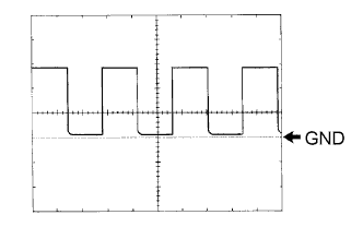
Below 1 V TW (A9-32) - GND (A9-29) P - L Water temperature signal Ignition switch ON Pulse generation TACO (A9-33) - GND (A9-29) B-W - L Tachometer signal Engine running Pulse generation
(see waveform 1)
PTC1 (A9-3) - GND (A9-29) R-W - L PTC heater relay signal Ignition switch START
Heater switch ON
Temperature Control knob: Max HOT
Coolant temperature 65 °C (149°F) or lower
Blower switch ON
Below 1 V PTC1 (A9-3) - GND (A9-29) GR - L PTC heater relay signal Ignition switch START
Heater switch OFF
Temperature Control knob: Max HOT
Coolant temperature 65 °C (149°F) or lower
Blower switch ON
10 to 14 V PTC2 (A9-2) - GND (A9-29) GR - L PTC heater relay signal Ignition switch START
Heater switch ON
Temperature Control knob: Max HOT
Coolant temperature 65 °C (149°F) or lower
Blower switch ON
Below 1 V PTC2 (A9-2) - GND (A9-29) GR - L PTC heater relay signal Ignition switch START
Heater switch OFF
Temperature Control knob: Max HOT
Coolant temperature 65 °C (149°F) or lower
Blower switch ON
10 to 14 V
-
If the result is not as specified, the air conditioning amplifier may have a malfunction.
-
-
Inspect using an oscilloscope.
-
Waveform 1 (Reference)
Item Content Symbols (Terminal No.) TACO (A9-33) - GND (A9-29) Tool Setting 5 V/DIV., 20 msec./DIV. Condition Engine idling Tech Tips
As engine speed increases, the wavelength shortens.
-
-
-
CHECK HEATER AMPLIFIER ASSEMBLY (w/ Viscous Heater)
-
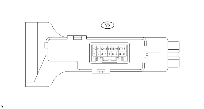
Disconnect the V6 viscous heater amplifier connector.
-
Measure the voltage and resistance of the wire harness side connector.
Symbols (Terminal NO.) Wiring Color Terminal Description Condition Specified Condition +B (V6-9) - GND (V6-15) L-Y - L Viscous heater MGC power supply Always 10 to 14 V IG (V6-1) - GND (V6-15) R-L- L Power source (IG) Ignition switch OFF Below 1 V IG (V6-1) - GND (V6-15) R-L- L Power source (IG) Ignition switch ON 10 to 14 V GND (V6-15) - Body ground L - Body ground Ground Always Below 1 Ω BLW (V6-2) - GND (V6-15) R-L - L Max HOT switch signal Temperature control knob: Max HOT Below 1 Ω BLW (V6-2) - GND (V6-15) R-L - L Max HOT switch signal Temperature control knob: except Max HOT 10k Ω or higher HLS (V6-10) - GND (V6-15) G - L Light control switch signal Light control switch ON 10 to 14 V HLS (V6-10) - GND (V6-15) G - L Light control switch signal Light control switch OFF Below 1 Ω
-
If the result is not as specified, there may be a malfunction on the wire harness side.
-
-
Reconnect the V6 viscous heater amplifier connector.
-
Measure the voltage and resistance of the wire harness side connector
Symbols (Terminal NO.) Wiring Color Terminal Description Condition Specified Condition MGCA (V6-18) - GND (V6-15) B -L Magnet clutch signal Ignition switch START
Magnet clutch is engaged
Below 1 V MGCA (V6-18) - GND (V6-15) B -L Magnet clutch signal Ignition switch START
Magnet clutch is not engaged
10 to 14 V ACT (V6-12) - GND (V6-15) R-L - L*1
V - L*2
Viscous heater permit signal Ignition switch START
Heater switch ON
Temperature control knob: Max HOT
Blower switch ON
Coolant temperature 65 °C (149°F) or more
Below 1 V ACT (V6-12) - GND (V6-15) R-L - L*1
V - L*2
Viscous heater permit signal Ignition switch START
Heater switch OFF
Temperature control knob: except Max HOT
Blower switch OFF
Coolant temperature 65 °C (149°F) or more
10 to 14 V AC2 (V6-5) - GND (V6-15) BR - L Viscous heater ON signal Ignition switch START
Heater switch ON
Temperature control knob: Max HOT
Blower switch ON
Coolant temperature 65 °C (149°F) or more
Above 7.8 V AC2 (V6-5) - GND (V6-15) BR - L Viscous heater ON signal Ignition switch START
Heater switch OFF
Temperature control knob: except Max HOT
Blower switch ON
Coolant temperature 65 °C (149°F) or more
Below 1 V BLW (V6-2) - GND (V6-15) R-L - L Max HOT switch signal Ignition switch ON
Temperature control knob: Max HOT
Blower switch ON
10 to 14 V BLW (V6-2) - GND (V6-15) R-L - L Max HOT switch signal Ignition switch ON
Temperature control knob: except Max HOT
Blower switch ON
Below 1 V SWVC (V6-13) - GND (V6-15) L-O - L Heater switch input signal Ignition switch START
Heater switch ON
Temperature control knob: Max HOT
Blower switch ON
Coolant temperature 65 °C (149°F) or more
Below 1 V SWVC (V6-13) - GND (V6-15) L-O - L Heater switch input signal Ignition switch START
Heater switch OFF
Temperature control knob: except Max HOT
Blower switch ON
Coolant temperature 65 °C (149°F) or more
10 to 14 V SWIN (V6-8) - ND (V6-15) P - L Heater switch indicator light signal Ignition switch START
Heater switch ON
Temperature control knob: Max HOT
Blower switch ON
Coolant temperature 65 °C (149°F) or more
10 to 14 V SWIN (V6-8) - GND P - L Heater switch indicator light signal Ignition switch START
Heater switch OFF
Temperature control knob: except Max HOT
Blower switch ON
Coolant temperature 65 °C (149°F) or more
Below 1 V TW (V6-4) - GND (V6-15) P - L Water temperature signal Ignition switch START Pulse generation TACO (V6-11) - GND (V6-15) B-W - L Tachometer signal Engine running Pulse generation
(see waveform 1)
ALT (V6-14) - GND (V6-15) G - L Generator Engine running Pulse generation PCT1 (V6-6) - GND (V6-15) R-W - L PTC heater relay signal Ignition switch START
Heater switch ON
Temperature control knob: Max HOT
Blower switch ON
Coolant temperature: 65°C (149°F) or lower
10 to 14 V PTC1 (V6-6) - GND (V6-15) R-W - L PTC heater relay signal Ignition switch START
Heater switch OFF
Temperature control knob: except Max HOT
Blower switch OFF
Coolant temperature: 65°C (149°F) or lower
Below 1 V PTC2 (V6-7) GND (V6-15) GR - L PTC heater relay signal Ignition switch START
Heater switch ON
Temperature control knob: Max HOT
Blower switch ON
Coolant temperature: 65°C (149°F) or lower
10 to 14 V PTC2 (V6-7) - GND (V6-15) GR - L PTC heater relay signal Ignition switch START
Heater switch OFF
Temperature control knob: except Max HOT
Blower switch OFF
Coolant temperature: 65°C (149°F) or lower
Below 1 V
-
*1: LHD
-
*2: RHD
If the result is not as specified, the heater amplifier may have a malfunction.
-
-
Inspect using an oscilloscope.
-
Waveform 1 (Reference)
Item Content Symbols (Terminal No.) TACO (V6-11) - GND (V6-15) Tool Setting 5 V/DIV., 20 msec./DIV. Condition Engine idling Tech Tips
As engine speed increases, the wavelength shortens.
-
-
-
CHECK ECM
-
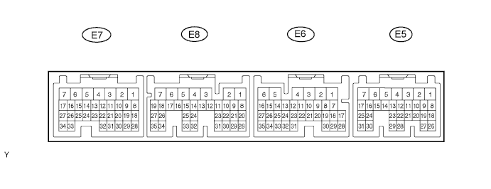
Measure the voltage of the connectors.
-
2KD-FTV
w/ Hot gas heater Symbols (Terminal NO.) Wiring color Terminal Description Condition Specified Condition ACT (E6-19) - E01 (E8-7) R-L - W-B Magnet on permit signal Ignition switch START
Heater switch OFF
Blower switch ON
A/C switch OFF
Below 1 V ACT (E6-19) - E01 (E8-7) R-L - W-B Magnet on permit signal Ignition switch START
Heater switch ON
Blower switch ON
A/C switch ON
10 to 14 V AC1 (E6-18) - E01 (E8-7) Y - W-B Idle-up request signal Ignition switch START
Magnet clutch is engaged
Below 1 V AC1 (E6-18) - E01 (E8-7) Y - W-B Idle-up request signal Ignition switch START
Magnet clutch is not engaged
10 to 14 V HSW (E6-20) - E01 (E8-7) L-W - W-B Heater switch output signal for idle-up Ignition switch START
Blower switch ON
Power heater switch ON
Temperature control knob: Max HOT
Below 1 V HSW (E6-20) - E01 (E8-7) L-W - W-B Heater switch output signal for idle-up Ignition switch START
Blower switch OFF
Power heater switch OFF
Temperature control knob: Max HOT
10 to 14 V THWO (E5-2) - E01 (E8-7) P -W-B Ignition switch ON Ignition switch START Pulse generation TACH (E5-4) - E01 (E8-7) B-W - W-B Tachometer signal Engine running Pulse generation (see waveform 1) w/ Viscous heater Symbols (Terminal NO.) Wiring color Terminal Description Condition Specified Condition ACT (E6-19) - E01 (E8-7) R-L - W-B*1
V - W-B*2
Viscous heater permit signal Ignition switch START
Heater switch OFF
Blower switch ON
Coolant temperature: 65°C (149°F) or lower
Temperature control knob: except Max HOT
Below 1 V ACT (E6-19) - E01 (E8-7) R-L - W-B*1
V - W-B*2
Viscous heater permit signal Ignition switch START
Heater switch ON
Blower switch ON
Coolant temperature: 65°C (149°F) or lower
Temperature control knob: Max HOT
10 to 14 V AC1 (E6-18) - E01 (E8-7) BR - W-B Viscous heater on signal Ignition switch START
Viscous magnet clutch is engaged
Below 1 V AC1 (E6-18) - E01 (E8-7) BR - W-B Viscous heater on signal Ignition switch START
Viscous magnet clutch is not engaged
10 to 14 V THWO (E5-2) - E01 (E8-7) P -W-B Ignition switch ON Ignition switch START Pulse generation TACH (E5-4) - E01 (E8-7) B-W - W-B Tachometer signal Engine running Pulse generation (see waveform 1) Tech Tips
*1: LHD
*2: RHD
-
If the result is not as specified, the ECM may have a malfunction.
-
-
-
Inspect using an oscilloscope.
-
Waveform 1 (Reference)
Item Content Symbols (Terminal No.) TACH (E5-4) - E01 (E8-7) Tool Setting 5 V/DIV., 20 msec./DIV. Condition Engine idling Tech Tips
As engine speed increases, the wavelength shortens.
-
-