FRONT AXLE HUB ON-VEHICLE INSPECTION
CAUTION / NOTICE / HINT
When the brake pedal is first depressed after replacing the brake pads or pushing back the disc brake piston, DTC C1214 may be output. As there is no malfunction, clear the DTC.
While the auxiliary battery is connected, even if the power switch is off, the brake control system activates when the brake pedal is depressed or the door courtesy switch is turned on. Therefore, even if only brake shoes are to be removed and installed, be sure to perform the Disable Brake Control procedure and disconnect the cable from the negative (-) terminal of the auxiliary battery before beginning work.
Use the same procedure for the RH and LH sides.
The procedure listed below is for the LH side.
PROCEDURE
PRECAUTION
Note:After turning the power switch off, waiting time may be required before disconnecting the cable from the negative (-) auxiliary battery terminal. Therefore, make sure to read the disconnecting the cable from the negative (-) auxiliary battery terminal notice before proceeding with work.
DISABLE BRAKE CONTROL
REMOVE FRONT WHEEL
DISCONNECT FRONT FLEXIBLE HOSE
DISCONNECT FRONT DISC BRAKE CALIPER ASSEMBLY LH
REMOVE FRONT DISC
for 16 inch Front Disc Brake:Click here
for 17 inch Front Disc Brake:Click here
INSPECT FRONT AXLE HUB BEARING LOOSENESS
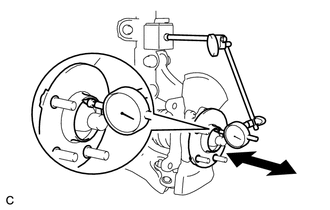
Using a dial indicator, check for looseness near the center of the front axle hub sub-assembly.
Maximum
0.05 mm (0.00197 in.)
Note:Make sure that the dial indicator is set perpendicular to the measurement surface.
If the looseness is more than the maximum, replace the front axle hub sub-assembly.
INSPECT FRONT AXLE HUB RUNOUT
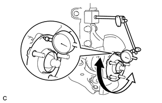
Using a dial indicator, check for runout on the surface of the front axle hub sub-assembly outside the front hub bolt.
Maximum
0.05 mm (0.00197 in.)
Note:Make sure that the dial indicator is set perpendicular to the measurement surface.
If the runout is more than the maximum, replace the front axle hub sub-assembly.
INSTALL FRONT DISC
for 16 inch Front Disc Brake:Click here
for 17 inch Front Disc Brake:Click here
CONNECT FRONT DISC BRAKE CALIPER ASSEMBLY LH
CONNECT FRONT FLEXIBLE HOSE
INSTALL FRONT WHEEL
CONNECT CABLE TO NEGATIVE AUXILIARY BATTERY TERMINAL
Connect the cable to the negative (-) auxiliary battery terminal and tighten the nut.
5.4 N*m
55 kgf*cm
48 in.*lbf
PERFORM INITIALIZATION