TRANSFER ASSEMBLY DISASSEMBLY
-
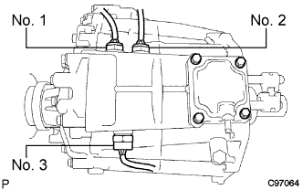
REMOVE TRANSFER INDICATOR SWITCH
-
Remove the switches and gaskets.
Tech Tips
Indicator switch:
No. 1 Indicator switch (neutral position) for A/T No. 2 Indicator switch (L4 position) for A/T or M/T w/ ABS No. 3 Indicator switch (4WD) for A/T and M/T
-
-
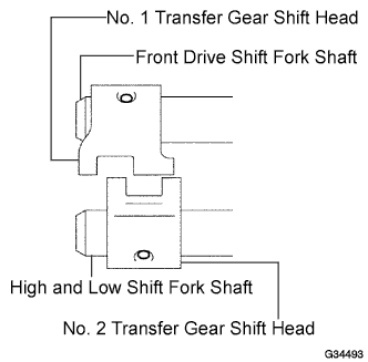
REMOVE TRANSFER GEAR SHIFT HEAD (for Adapter on Type)
-
Using a pin punch and hammer, remove the 2 slotted pins from the No. 1 and No. 2 gear shift heads.
-
Remove the No. 1 and No. 2 gear shift heads from the front drive shift fork shaft, and high and low shift fork shaft.
-
-
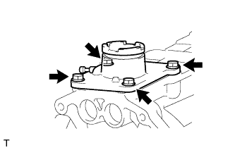
REMOVE TRANSFER CONTROL SHIFT LEVER RETAINER SUB-ASSEMBLY (for Transfer on Type)
-
Remove the 4 bolts and retainer.
-
-
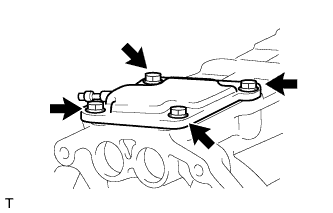
REMOVE TRANSFER CASE COVER SUB-ASSEMBLY (for Adapter on Type)
-
Remove the 4 bolts and case cover.
-
-
REMOVE BREATHER OIL DEFLECTOR
-
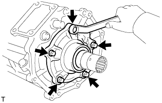
REMOVE TRANSFER BEARING RETAINER SUB-ASSEMBLY
-
Remove the 5 bolts and bearing retainer.
Tech Tips
If necessary, tap the bearing retainer with a plastic-faced hammer to remove it.
-
-
REMOVE TRANSFER COVER OIL SEAL
-
Using a screwdriver and hammer, tap out the oil seal from the bearing retainer.
Note
Be careful not to damage the oil seal and bearing retainer contact surfaces.
-
-
REMOVE OUTPUT SHAFT COMPANION FLANGE SUB-ASSEMBLY (for Front)
-
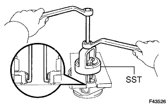
Using a chisel and hammer, loosen the staked part of the lock nut.
-
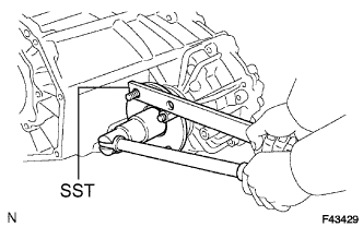
Using SST to hold the companion flange, remove the lock nut.
- SST
- 09330-00021
-
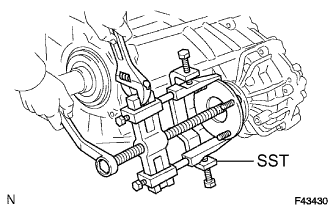
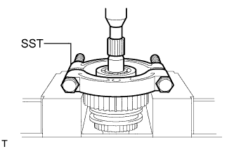
Using SST, remove the companion flange.
- SST
- 09950-40011 ( 09951-04020, 09952-04010, 09953-04030, 09954-04010, 09955-04051, 09957-04010, 09958-04011 )
-
-
REMOVE TRANSFER OUTPUT SHAFT COMPANION FLANGE OIL SEAL (for Front)
-
Using a screwdriver and hammer, tap out the oil seal from the companion flange.
Note
Be careful not to damage the oil seal and companion flange contact surfaces.
-
-
REMOVE OUTPUT SHAFT COMPANION FLANGE SUB-ASSEMBLY (for Rear)
-
Remove the companion flange (rear) in the same way as the companion flange (front).
- SST
- 09330-00021
- 09950-40011 ( 09951-04020, 09952-04010, 09953-04030, 09954-04010, 09955-04051, 09957-04010, 09958-04011 )
-
-
REMOVE TRANSFER OUTPUT SHAFT COMPANION FLANGE OIL SEAL (for Rear)
-
Using a screwdriver and hammer, tap out the oil seal from the companion flange.
Note
Be careful not to damage the oil seal and companion flange contact surfaces.
-
-
REMOVE SPEEDOMETER SENSOR
-
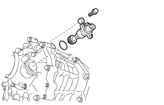
Remove the bolt and speedometer sensor from the transfer.
-
Remove the O-ring from the speedometer sensor.
-
-
REMOVE TRANSFER EXTENSION HOUSING SUB-ASSEMBLY
-
Remove the 5 bolts and extension housing.
Tech Tips
If necessary, tap the extension housing with a plastic-faced hammer to remove it.
-
-
REMOVE TRANSFER EXTENSION HOUSING TYPE T OIL SEAL
-
Using a screwdriver and hammer, tap out the oil seal.
Note
Be careful not to damage the oil seal and extension housing contact surfaces.
-
-
REMOVE TRANSFER OUTPUT SHAFT WASHER
-
REMOVE TRANSFER SPEEDOMETER DRIVE GEAR
-
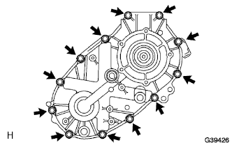
REMOVE REAR TRANSFER CASE
-
Remove the 12 bolts and clamp.
-
Remove the rear case.
Tech Tips
If necessary, tap the rear case with a plastic-faced hammer to remove it.
-
-
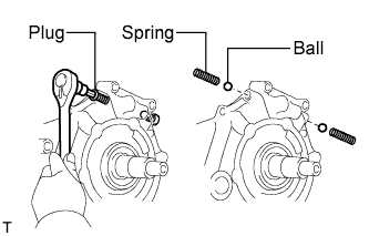
REMOVE FRONT TRANSFER DRIVE SHIFT FORK SHAFT
-
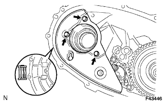
Using a hexagon wrench, remove the 2 plugs.
-
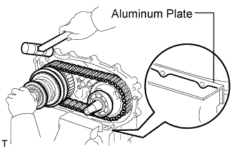
Using a magnetic finger, remove the 2 springs and 2 balls from both holes.
-
Mount the case rear in a vise.
Note
Place aluminum plates on the vise to prevent damage to the case rear.
-
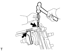
Using a pin punch and hammer, tap out the 2 slotted pins from the shift shaft stopper and No. 2 gear shift fork.
-
Hold the shift fork shaft in place by hand when removing the pin punch.
-
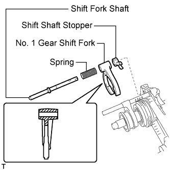
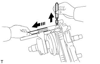
Remove the shift fork shaft, No. 1 gear shift fork, spring and shift shaft stopper.
-
Using a magnetic finger, remove the straight pin.
-
-
REMOVE TRANSFER HIGH AND LOW SHIFT FORK SHAFT
-
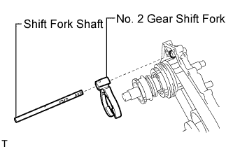
Remove the shift fork shaft and No. 2 gear shift fork.
-
-
REMOVE TRANSFER REAR OUTPUT SHAFT, FRONT TRANSFER DRIVE CHAIN AND TRANSFER DRIVEN SPROCKET
-
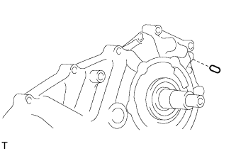
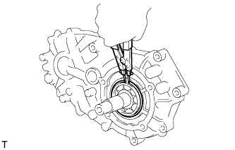
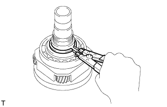
Using a snap ring expander, remove the snap ring.
-
Using a plastic-faced hammer, carefully tap the case rear, and remove the output shaft together with the drive chain and driven sprocket.
-
Remove the output shaft and driven sprocket from the drive chain.
-
-
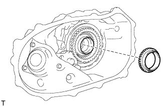
REMOVE TRANSFER DRIVEN SPROCKET BEARING
-
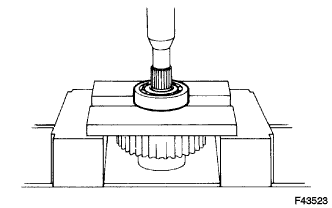
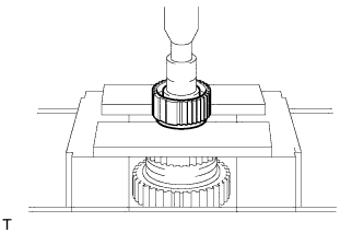
Using a press, press out the bearing.
Note
Be careful not to drop or damage the driven sprocket.
-
-
REMOVE TRANSFER INPUT GEAR RADIAL BALL BEARING
-
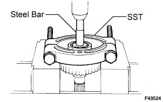
Using SST, a press and steel bar, press out the bearing.
- SST
- 09555-55010
Note
Be careful not to damage the driven sprocket.
-
-
REMOVE NO. 1 TRANSFER CASE PLUG (for Filler)
-
Remove the filler plug and gasket.
-
-
REMOVE NO. 1 TRANSFER CASE PLUG (for Drain)
-
Remove the drain plug and gasket.
-
-
REMOVE TRANSFER OIL SEPARATOR SUB-ASSEMBLY
-
Remove the 3 bolts and oil separator.
-
-
REMOVE TRANSFER CASE MAGNET
-
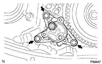
REMOVE TRANSFER OIL PUMP BODY SUB-ASSEMBLY
-
Remove the 3 bolts and oil pump body.
-
-
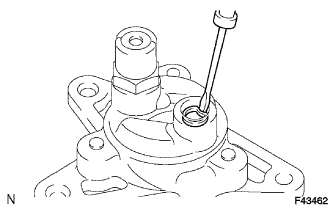
REMOVE TRANSFER OIL PUMP BODY O-RING
-
Using a screwdriver, remove the O-ring from the oil pump body.
Note
Be careful not to damage the oil pump body.
-
-
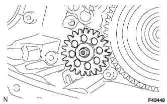
REMOVE TRANSFER OIL PUMP GEAR
-
Remove the nut and oil pump gear.
-
-
REMOVE FRONT TRANSFER DRIVE CLUTCH SYNCHRONIZER RING (for Manual Transmission)
-
Remove the synchronizer ring from the planetary gear.
-
-
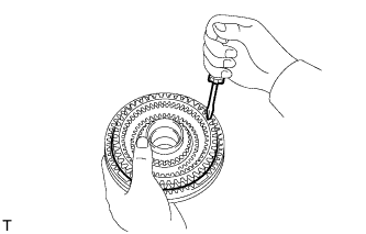
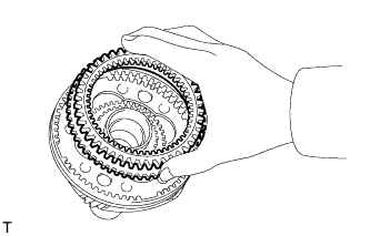
REMOVE TRANSFER LOW PLANETARY GEAR ASSEMBLY WITH TRANSFER INPUT SHAFT
-
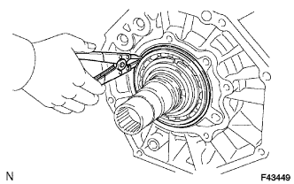
Using a snap ring expander, remove the snap ring.
-
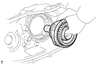
Remove the low planetary gear with the input shaft.
-
-
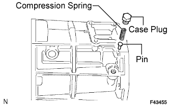
REMOVE TRANSFER CASE PLUG
-
REMOVE COMPRESSION SPRING
-
REMOVE PIN
-
REMOVE TRANSFER LOW PLANETARY RING GEAR
-
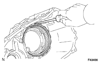
Using a screwdriver, pry out the snap ring.
Note
Be careful not to damage the case front.
-
Remove the ring gear from the case front.
-
-
REMOVE TRANSFER CASE OIL SEAL
-
Using a screwdriver and hammer, tap out the oil seal (No. 1).
-
Using a screwdriver and hammer, tap out the oil seal (No. 2).
Note
Be careful not to damage the oil seal and case front contact surfaces.
-
-
REMOVE TRANSFER LOW PLANETARY GEAR SPLINE PIECE
-
Using a screwdriver, pry out the snap ring.
Note
Be careful not to damage the low planetary gear.
-
Remove the spline piece.
-
-
REMOVE TRANSFER OUTPUT SHAFT FRONT NEEDLE ROLLER BEARING
-
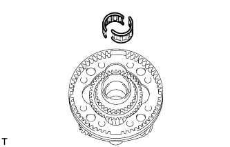
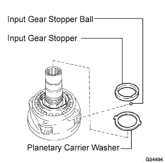
REMOVE TRANSFER INPUT GEAR STOPPER SHAFT SNAP RING
-
Using a snap ring expander, remove the snap ring.
-
-
REMOVE TRANSFER INPUT GEAR STOPPER
-
REMOVE TRANSFER INPUT GEAR STOPPER BALL
-
REMOVE MANUAL TRANSFER PLANETARY CARRIER WASHER
-
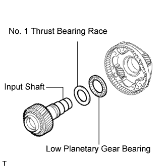
REMOVE TRANSFER INPUT SHAFT
-
REMOVE NO. 1 TRANSFER THRUST BEARING RACE
-
REMOVE TRANSFER LOW PLANETARY GEAR BEARING
-
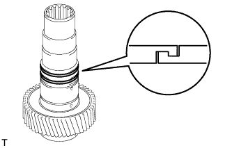
REMOVE NO. 1 TRANSFER INPUT SHAFT SEAL RING
-
Remove the 2 seal rings.
-
-
REMOVE TRANSFER INPUT SHAFT BEARING
-
Using a snap ring expander, remove the snap ring.
-
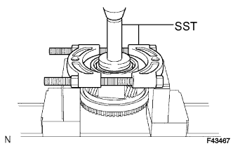
Using SST and a press, press out the bearing.
- SST
- 09554-30011
- 09555-55010
Note
Be careful not to drop or damage the low planetary gear.
-
-
REMOVE TRANSFER LOW PLANETARY GEAR BEARING
-
Using SST, remove the bearing.
- SST
- 09612-65014 ( 09612-01030, 09612-01050 )
Note
Hang SST securely between the bearing and low planetary gear.
-
-
REMOVE TRANSFER CLUTCH HUB (for Manual Transmission)
-
Using a snap ring expander, remove the snap ring.
-
Remove the high and low clutch sleeve, 3 shifting keys and 2 shifting key springs.
-
Using a press, press out the clutch hub.
Note
Be careful not to drop or damage the clutch hub.
-
-
REMOVE TRANSFER CLUTCH HUB (for Automatic Transmission)
-
Using a snap ring expander, remove the snap ring.
-
Remove the high and low clutch sleeve.
-
Using a press, press out the clutch hub.
Note
Be careful not to drop or damage the clutch hub.
-
-
REMOVE TRANSFER DRIVE SPROCKET SUB-ASSEMBLY (for A.D.D. Manual Shift Type)
-
Using SST and a press, press out the bearing.
- SST
- 09555-55010
Note
Be careful not to drop or damage the output shaft.
-
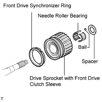
Remove the spacer and ball.
-
Remove the drive sprocket with front drive clutch sleeve.
-
Remove the needle roller bearing.
-
Remove the front drive synchronizer ring.
-
Remove the front drive sleeve, 3 shifting keys and 2 shifting key springs from the drive sprocket.
-
-
REMOVE TRANSFER DRIVE SPROCKET SUB-ASSEMBLY (for Normal Shift Type)
-
Using SST and a press, press out the bearing.
- SST
- 09555-55010
Note
Be careful not to drop or damage the output shaft.
-
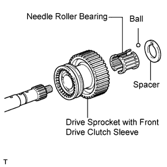
Remove the spacer and ball.
-
Remove the drive sprocket with front drive clutch sleeve.
-
Remove the needle roller bearing.
-