ENGINE UNIT DETAILS VVT-i CONTROLLER
CONSTRUCTION
The VVT-i controllers (camshaft timing sprocket assembly and camshaft timing exhaust gear assembly) consist of an outer housing that is driven by the timing chain sprocket, and a vane that is coupled to camshaft.
The camshaft timing sprocket assembly uses 3 vanes.
The camshaft timing exhaust gear assembly uses 4 vanes.
The oil pressure sent from the advanced or retarded side path at the intake camshaft (camshaft) and exhaust camshaft (No. 2 camshaft) causes rotation in the VVT-i controller vane circumferential direction to vary the intake and exhaust valve timing continuously.
When the engine is stopped, a lock pin locks the intake camshaft (camshaft) at the most retarded position and the exhaust camshaft (No. 2 camshaft) at the most advanced position, to ensure that the engine starts properly.
An advance assist spring is provided on the camshaft timing exhaust gear assembly. This spring applies torque in the advance direction when the engine is stopped, thus ensuring the engagement of the lock pin.
Figure 1. Intake VVT-i Controller (Camshaft Timing Sprocket Assembly) 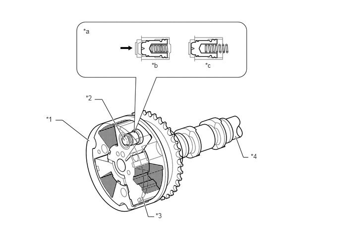
*1
Housing
*2
Lock Pin
*3
Vane
*4
Intake Camshaft (Camshaft)
*a
Lock Pin Operation
*b
Engine Operating
*c
Engine Stopped
-
-

Oil Pressure
-
-
Figure 2. Exhaust VVT-i Controller (Camshaft Timing Exhaust Gear Assembly) 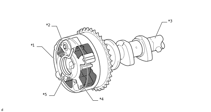
*1
Housing
*2
Lock Pin
*3
Exhaust Camshaft (No. 2 Camshaft)
*4
Vane
*5
Advance Assist Spring
-
-