INPUT SHAFT INSPECTION
PROCEDURE
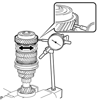
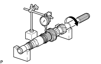
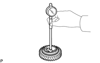
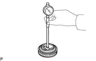
INSPECT 6TH GEAR THRUST CLEARANCE
-
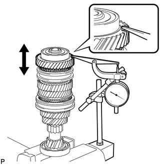
Using a dial indicator, measure the 6th gear thrust clearance.
Standard clearance
0.15 to 0.43 mm (0.00591 to 0.0169 in.)
Maximum clearance
0.43 mm (0.0169 in.)
If the clearance is more than the maximum, replace the No. 3 transmission clutch hub, 6th gear or input shaft. Replace the part or parts determined to be the most likely cause of the problem.
-
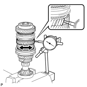
INSPECT 5TH GEAR THRUST CLEARANCE
-
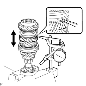
Using a dial indicator, measure the 5th gear thrust clearance.
Standard clearance
0.15 to 0.43 mm (0.00591 to 0.0169 in.)
Maximum clearance
0.43 mm (0.0169 in.)
If the clearance is more than the maximum, replace the No. 3 transmission clutch hub, 5th gear or input shaft. Replace the part or parts determined to be the most likely cause of the problem.
-
INSPECT 4TH GEAR THRUST CLEARANCE
-
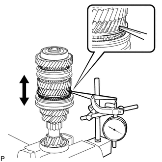
Using a dial indicator, measure the 4th gear thrust clearance.
Standard clearance
0.15 to 0.56 mm (0.00591 to 0.0220 in.)
Maximum clearance
0.56 mm (0.0220 in.)
If the clearance is more than the maximum, replace the No. 2 transmission clutch hub, 4th gear or input shaft. Replace the part or parts determined to be the most likely cause of the problem.
-
INSPECT 3RD GEAR THRUST CLEARANCE
-
Using a dial indicator, measure the 3rd gear thrust clearance.
Standard clearance
0.15 to 0.43 mm (0.00591 to 0.0169 in.)
Maximum clearance
0.43 mm (0.0169 in.)
If the clearance is more than the maximum, replace the No. 2 transmission clutch hub, 3rd gear or input shaft. Replace the part or parts determined to be the most likely cause of the problem.
-
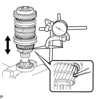
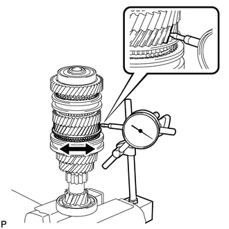
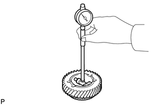
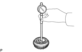
INSPECT 6TH GEAR RADIAL CLEARANCE
-
Using a dial indicator, measure the 6th gear radial clearance between the gear and shaft.
Standard clearance
0.009 to 0.045 mm (0.000354 to 0.00177 in.)
Maximum clearance
0.045 mm (0.00177 in.)
If the clearance is more than the maximum, replace the 6th gear, 6th gear needle roller bearing, inner 6th gear bearing race or input shaft. Replace the part or parts determined to be the most likely cause of the problem.
-
INSPECT 5TH GEAR RADIAL CLEARANCE
-
Using a dial indicator, measure the 5th gear radial clearance between the gear and shaft.
Standard clearance
0.009 to 0.045 mm (0.000354 to 0.00177 in.)
Maximum clearance
0.045 mm (0.00177 in.)
If the clearance is more than the maximum, replace the 5th gear, 5th gear needle roller bearing, inner 5th gear bearing race or input shaft. Replace the part or parts determined to be the most likely cause of the problem.
-
INSPECT 4TH GEAR RADIAL CLEARANCE
-
Using a dial indicator, measure the 4th gear radial clearance between the gear and shaft.
Standard clearance
0.009 to 0.050 mm (0.000354 to 0.0197 in.)
Maximum clearance
0.050 mm (0.0197 in.)
If the clearance is more than the maximum, replace the 4th gear, 4th gear needle roller bearing or input shaft. Replace the part or parts determined to be the most likely cause of the problem.
-
INSPECT 3RD GEAR RADIAL CLEARANCE
-
Using a dial indicator, measure the 3rd gear radial clearance.
Standard clearance
0.009 to 0.050 mm (0.000354 to 0.0197 in.)
Maximum clearance
0.050 mm (0.0197 in.)
If the clearance is more than the maximum, replace the 3rd gear, 3rd gear needle roller bearing or input shaft. Replace the part or parts determined to be the most likely cause of the problem.
-
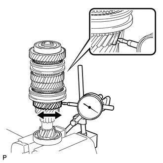
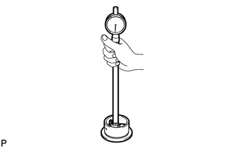
INSPECT INPUT SHAFT
-
Using a dial indicator, check the input shaft runout.
Maximum runout
0.015 mm (0.000590 in.)
If the runout is more than the maximum, replace the input shaft.
-
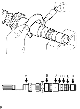
Using a micrometer, measure the outer diameter of the input shaft journal surface at the locations indicated.
Standard outer diameter
Journal A
25.002 to 25.017 mm (0.9843 to 0.9849 in.)
Journal B
37.485 to 37.500 mm (1.4758 to 1.4763 in.)
Journal C
31.690 to 31.700 mm (1.2476 to 1.2480 in.)
Journal D
27.990 to 28.000 mm (1.1020 to 1.1023 in.)
Minimum outer diameter
Journal A
25.002 mm (0.9843 in.)
Journal B
37.485 mm (1.4758 in.)
Journal C
31.690 mm (1.2476 in.)
Journal D
27.990 mm (1.1020 in.)
If the outer diameter is less than the minimum, replace the input shaft.
-
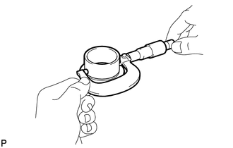
INSPECT INNER 6TH GEAR BEARING RACE
-
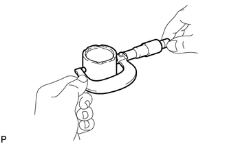
Using a micrometer, measure the outer diameter of the inner 6th gear bearing race.
Standard outer diameter
35.09 to 35.10 mm (1.3815 to 1.3818 in.)
Minimum outer diameter
35.09 mm (1.3815 in.)
If the outer diameter is less than the minimum, replace the inner 6th gear bearing race.
-
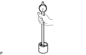
Using a cylinder gauge, measure the inside diameter of the inner 6th gear bearing race.
Standard inside diameter
28.005 to 28.020 mm (1.1026 to 1.1031 in.)
Maximum inside diameter
28.020 mm (1.1031 in.)
If the inside diameter is more than the maximum, replace the inner 6th gear bearing race.
-
INSPECT INNER 5TH GEAR BEARING RACE
-
Using a micrometer, measure the outer diameter of the inner 5th gear bearing race.
Standard outer diameter
37.49 to 37.50 mm (1.4760 to 1.4763 in.)
Minimum outer diameter
37.49 mm (1.47560 in.)
If the outer diameter is less than the minimum, replace the inner 5th gear bearing race.
-
Using a cylinder gauge, measure the inside diameter of the inner 5th gear bearing race.
Standard inside diameter
31.705 to 31.720 mm (1.2483 to 1.2488 in.)
Maximum inside diameter
31.720 mm (1.2488 in.)
If the inside diameter is more than the maximum, replace the inner 5th gear bearing race.
-
INSPECT 6TH GEAR SUB-ASSEMBLY
-
Using a cylinder gauge, measure the inside diameter of the 6th gear sub-assembly.
Standard inside diameter
40.109 to 40.125 mm (1.5791 to 1.5797 in.)
Maximum inside diameter
40.125 mm (1.5797 in.)
If the inside diameter is more than the maximum, replace the 6th gear sub-assembly.
-
INSPECT 5TH GEAR
-
Using a cylinder gauge, measure the inside diameter of the 5th gear.
Standard inside diameter
42.509 to 42.525 mm (1.6736 to 1.6742 in.)
Maximum inside diameter
42.525 mm (1.6742 in.)
If the inside diameter is more than the maximum, replace the 5th gear.
-
INSPECT 4TH GEAR
-
Using a cylinder gauge, measure the inside diameter of the 4th gear.
Standard inside diameter
42.509 to 42.525 mm (1.6736 to 1.6742 in.)
Maximum inside diameter
42.525 mm (1.6742 in.)
If the inside diameter is more than the maximum, replace the 4th gear.
-
INSPECT 3RD GEAR
-
Using a cylinder gauge, measure the inside diameter of the 3rd gear.
Standard inside diameter
42.509 to 42.525 mm (1.6736 to 1.6742 in.)
Maximum inside diameter
42.525 mm (1.6742 in.)
If the inside diameter is more than the maximum, replace the 3rd gear.
-
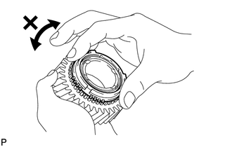
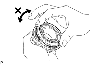
INSPECT NO. 5 SYNCHRONIZER RING
-
Check for wear and damage.
Coat the 6th gear cone with gear oil.
Coat the 5th gear cone with gear oil.
Turn the synchronizer ring in both directions while pushing it against the 6th gear cone and check that it locks in both directions.
If the synchronizer ring does not lock, replace the synchronizer ring.
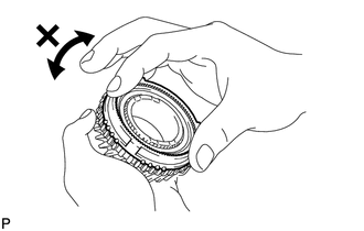
Turn the synchronizer ring in both directions while pushing it against the 5th gear cone and check that it locks in both directions.
If the synchronizer ring does not lock, replace the synchronizer ring.
-
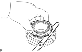
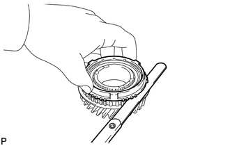
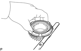
Using a feeler gauge, measure the clearance between the synchronizer ring and gear spline end.
Standard clearance
0.73 to 1.53 mm (0.0288 to 0.0602 in.)
Minimum clearance
0.73 mm (0.0288 in.)
If the clearance is less than the minimum, replace the synchronizer ring.
-
INSPECT OUTER 2ND SYNCHRONIZER RING
-
Check for wear and damage.
Coat the 4th gear cone with gear oil.
Turn the synchronizer ring in both directions while pushing it against the 4th gear cone and check that it locks in both directions.
If the synchronizer ring does not lock, replace the synchronizer ring.
-
Using a feeler gauge, measure the clearance between the synchronizer ring and gear spline end.
Standard clearance
0.78 to 1.58 mm (0.0308 to 0.0622 in.)
Minimum clearance
0.78 mm (0.0308 in.)
If the clearance is less than the minimum, replace the synchronizer ring.
-
INSPECT NO. 3 SYNCHRONIZER RING
-
Check for wear and damage.
Coat the 3rd gear cone with gear oil.
Turn the synchronizer ring in both directions while pushing it against the 3rd gear cone and check that it locks in both directions.
If the synchronizer ring does not lock, replace the synchronizer ring.
-
Using a feeler gauge, measure the clearance between the synchronizer ring and gear spline end.
Standard clearance
0.78 to 1.58 mm (0.0308 to 0.0622 in.)
Minimum clearance
0.78 mm (0.0308 in.)
If the clearance is less than the minimum, replace the synchronizer ring.
-
INSPECT NO. 2 TRANSMISSION HUB SLEEVE
-
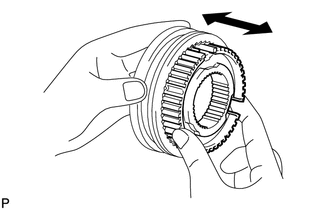
Check the sliding condition between the No. 2 transmission hub sleeve and No. 2 transmission clutch hub.
Check that the edges of the No. 2 transmission hub sleeve spline gear are not worn down.
-
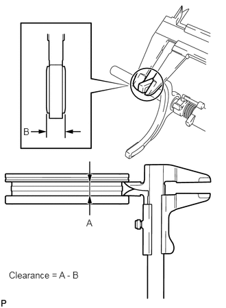
Using a vernier caliper, measure the width of the No. 2 transmission hub sleeve groove (A) and the thickness of the claw part on the No. 2 gear shift fork (B), and calculate the clearance.
Standard clearance (A - B)
0.1 to 0.5 mm (0.00394 to 0.0196 in.)
If the clearance is not as specified, replace the No. 2 transmission hub sleeve and No. 2 gear shift fork.
-
INSPECT NO. 3 TRANSMISSION HUB SLEEVE
-
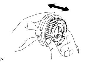
Check the sliding condition between the No. 3 transmission hub sleeve and No. 3 transmission clutch hub.
Check that the edges of the No. 3 transmission hub sleeve spline gear are not worn down.
-
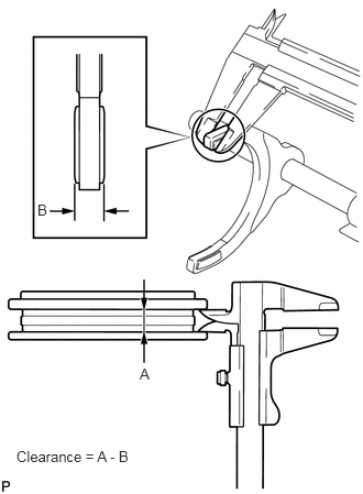
Using a vernier caliper, measure the width of the No. 3 transmission hub sleeve groove (A) and the thickness of the claw part on the No. 3 gear shift fork (B), and calculate the clearance.
Standard clearance (A - B)
0.1 to 0.5 mm (0.00394 to 0.0196 in.)
If the clearance is not as specified, replace the No. 3 transmission hub sleeve and No. 3 gear shift fork.
-