SFI SYSTEM, Diagnostic DTC:P2195, P2196
| DTC Code | DTC Name |
|---|---|
| P2195 | Oxygen (A/F) Sensor Signal Stuck Lean (Bank 1 Sensor 1) |
| P2196 | Oxygen (A/F) Sensor Signal Stuck Rich (Bank 1 Sensor 1) |
CAUTION / NOTICE / HINT
Tech Tips
These DTCs are related to the A/F sensor.
DESCRIPTION
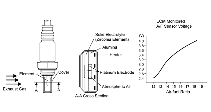
The Air-fuel Ratio (A/F) sensor generates a voltage* in response to the actual air-fuel ratio. The sensor output voltage provides feedback to the ECM. The ECM uses the feedback to control the air-fuel ratio. Using the sensor output voltage, the ECM determines the deviation from the stoichiometric air-fuel ratio, and regulates the injection time. If the A/F sensor is malfunctioning, the ECM is unable to control the air-fuel ratio accurately.
The A/F sensor is equipped with a heater which heats the zirconia element. The heater is also controlled by the ECM. When the intake air volume is low (the temperature of the exhaust gas is low), a current flows to the heater to heat the sensor to facilitate the detection of accurate oxygen concentration.
The A/F sensor is a planar type. The heat of the heater is conducted to the zirconia element through the alumina, accelerating sensor activation.
To obtain a high purification rate of carbon monoxide (CO), hydrocarbon (HC) and nitrogen oxide (NOx) in the exhaust gas, the Three-Way Catalytic Converter (TWC) is used. The TWC is most efficient when the air-fuel ratio is maintained near the stoichiometric air-fuel ratio.
Tech Tips
*: The voltage value changes inside the ECM only.
| DTC No. | DTC Detection Condition | Trouble Area |
|---|---|---|
| P2195 | Conditions (a) and (b) continue for 2 seconds or more: (a) A/F sensor voltage is more than 3.8 V (b) Rear oxygen sensor voltage is 0.15 V or more |
|
| P2196 | Conditions (a) and (b) continue for 2 seconds or more: (a) A/F sensor voltage is more than 2.8 V (b) Heated oxygen sensor voltage is less than 0.85 V |
|
Tech Tips
-
Sensor 1 refers to the sensor mounted before the TWC and is located near the engine assembly.
-
Sensor 2 refers to the sensor mounted after the TWC and is located far from the engine assembly.
-
When DTC P2195 and / or P2196 is detected, check the A/F sensor output voltage (AFS B1 S1) by selecting Powertrain / Engine and ECT / Data List on the intelligent tester.
-
The short-term fuel trim value can also be read using the intelligent tester.
-
The ECM controls the voltage of the A1A+ and A1A- terminals of the ECM to the fixed voltage. Therefore, the A/F sensor output voltage cannot be confirmed without the intelligent tester.
MONITOR DESCRIPTION
Under the air-fuel ratio feedback control, if the output voltage of the A/F sensor indicates RICH or LEAN for a certain period of time or more, the ECM concludes that there is a fault in the A/F sensor system. The ECM will turn on the MIL and a DTC is set.
Example:
If the A/F sensor output voltage is less than 2.8 V (too RICH) for 10 seconds even though the heated oxygen sensor output voltage is less than 0.85 V, the ECM sets DTC P2196 or DTC P2198. If the heated oxygen sensor output voltage is 0.15 V or more but the A/F sensor output voltage is more than 3.8 V (too LEAN) for 10 seconds, DTC P2195 is set.
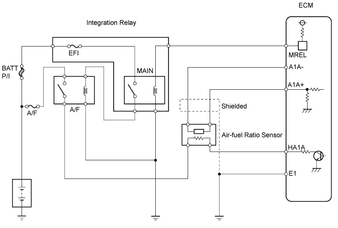
WIRING DIAGRAM
CONFIRMATION DRIVING PATTERN
(a) Connect the intelligent tester to the DLC3.
(b) Turn the ignition switch ON and turn the intelligent tester ON.
(c) Change the ECM from normal mode to check mode using the intelligent tester.
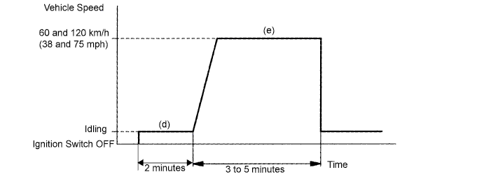
(d) Start the engine and warm it up with all the accessories turned OFF.
(e) Drive the vehicle at 60 to 120 km/h (38 to 75 mph), and maintain the engine speed at 1,400 to 3,200 rpm for 3 to 5 minutes.
Tech Tips
If a malfunction exists, the MIL will illuminate during step (e).
Note
If the conditions in this test are not strictly followed, no malfunction will be detected.
INSPECTION PROCEDURE
Tech Tips
Intelligent tester only:
Malfunctioning areas can be identified by performing the "Control the Injection Volume" function provided in the Active Test. The "Control the Injection Volume" function can help to determine whether the Air-fuel Ratio (A/F) sensor, heated oxygen (HO2) sensor and other potential trouble areas are malfunctioning.
The following instructions describe how to conduct the "Control the Injection Volume" operation using intelligent tester.
-
Connect the intelligent tester to the DLC3.
-
Start the engine and turn the intelligent tester ON.
-
Warm up the engine by running the engine at 2,500 rpm for approximately 90 seconds.
-
On the intelligent tester, select the following menu items: Powertrain / Engine and ECT/ Active Test / Control the Injection Volume.
-
Perform the "Control the Injection Volume" operation with the engine in an idling condition (press the right or left button to change the fuel injection volume).
-
Monitor the output voltage of the A/F and Heated oxygen sensors (AFS B1 S1 and O2S B1 S2) displayed on the tester.
Tech Tips
-
The "Control the Injection Volume" operation lowers the fuel injection volume by 12.5% or increases the injection volume by 24.8%.
-
Each sensor reacts in accordance with increases and decreases in the fuel injection volume.
| Standard | ||||||||||||||||||||
|---|---|---|---|---|---|---|---|---|---|---|---|---|---|---|---|---|---|---|---|---|
|
Note
The A/F sensor output has a few seconds of delay and the heated oxygen sensor output has about 20 seconds of delay at maximum.
| Case | A/F Sensor (Sensor 1) Output Voltage |
HO2 Sensor (Sensor 2) Output Voltage |
Main Suspected Trouble Areas | ||
|---|---|---|---|---|---|
| 1 | Injection Volume +24.8% -12.5% |
 |
Injection Volume +24.8% -12.5% |
|
- |
| Output Voltage More than 3.35 V Less than 3.0 V |
 |
Output Voltage More than 0.55 V Less than 0.4 V |
 |
||
| 2 | Injection Volume +24.8% -12.5% |
|
Injection Volume +24.8% -12.5% |
|
|
| Output Voltage Almost no reaction |
 |
Output Voltage More than 0.55 V Less than 0.4 V |
|
||
| 3 | Injection Volume +24.8% -12.5% |
|
Injection Volume +24.8% -12.5% |
|
|
| Output Voltage More than 3.35 V Less than 3.0 V |
|
Output Voltage Almost no reaction |
|
||
| 4 | Injection volume +24.8% -12.5% |
|
Injection Volume +24.8% -12.5% |
|
|
| Output Voltage Almost no reaction |
|
Output Voltage Almost no reaction |
|
||
-
The following "Control the Injection Volume" procedure enables the technician to check and graph the output voltage of both A/F sensor and heated oxygen sensor.
-
To display the graph, select the following menu items on the tester: View / Line graph.
Tech Tips
-
Read freeze frame data using the intelligent tester. Freeze frame data records the engine conditions when malfunctions are detected. When troubleshooting, freeze frame data can help determine if the vehicle was moving or stationary, if the engine was warmed up or not, if the air-fuel ratio was lean or rich, and other data from the time the malfunction occurred.
-
A low A/F sensor voltage could be caused by a rich air-fuel mixture. Check for conditions that would cause the engine to run with the rich air-fuel mixture.
-
A high A/F sensor voltage could be caused by a lean air-fuel mixture. Check for conditions that would cause the engine to run with the lean air-fuel mixture.
PROCEDURE
-
CHECK OTHER DTC OUTPUT (IN ADDITION TO A/F SENSOR DTC)
-
Connect the intelligent tester to the DLC3.
-
Turn the ignition switch ON and turn the intelligent tester ON.
-
Select the following menu items: Powertrain / Engine and ECT / DTC.
-
Read DTCs.
Result Display (DTC Output) Proceed to A/F sensor circuit DTCs A A/F sensor circuit DTCs and other DTCs B Tech Tips
If any other DTCs besides the A/F sensor DTCs are output, perform troubleshooting for those DTCs first.
B 
GO TO RELEVANT DTC CHART
A 
-
-
READ VALUE USING DATA LIST (OUTPUT VOLTAGE OF A/F SENSOR)
-
Connect the intelligent tester to the DLC3.
-
Start the engine and turn the intelligent tester ON.
-
Warm up the A/F sensor with the engine at 2,500 rpm for approximately 90 seconds.
-
On the intelligent tester, select the following menu items: Powertrain / Engine and ECT / Data List.
-
Select the following monitor items: AFS B1 S1 and Engine Speed.
-
Monitor the A/F sensor voltage carefully.
-
Check the A/F sensor voltage under the following conditions.
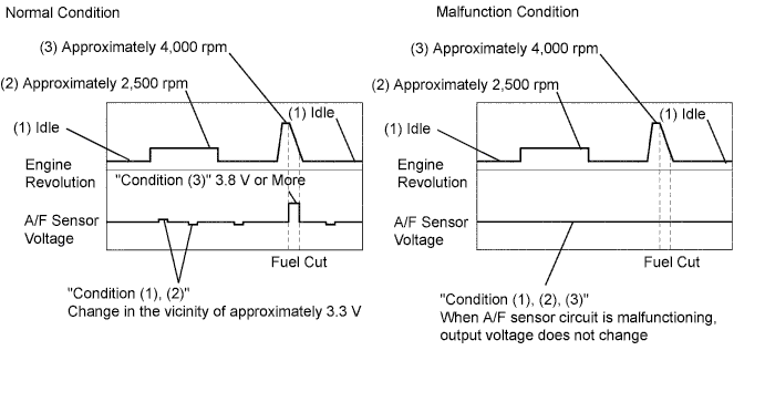
(1) Allow the engine to idle for 30 seconds.
(2) Run the engine at approximately 2,500 rpm (where the engine rpm is not suddenly changed).
(3) Raise the engine speed to 4,000 rpm and quickly release the accelerator pedal so that the throttle valve is fully closed.
Standard Condition A/F Sensor Voltage Variation Reference (1) and (2) Changes at approx. 3.3 V (0.66 V*) Between 3.1 and 3.5 V (0.62 and 0.7 V*) (3) Increases to 3.8 V (0.76 V*) or more This occurs during engine deceleration
(when fuel-cut performed)
Tech Tips
*: Voltage when not using intelligent tester.
-
For more information, see the diagrams below.
Tech Tips
-
If the output voltage of the A/F sensor remains at approximately 3.3 V (0.66 V*) (see Malfunction Condition diagram) under any condition as well as the above conditions, the A/F sensor may have an open circuit (this will happen also when the A/F sensor heater has an open circuit).
-
If the output voltage of the A/F sensor remains at a certain value of approximately 3.8 V (0.67 V*) or more, or 2.8 V (0.56 V*) or less (see Malfunction Condition diagram) under any condition as well as the above conditions, the A/F sensor may have a short circuit.
-
The ECM will stop fuel injection (fuel-cut) during engine deceleration. This will cause a lean condition and should result in a momentary increase in the A/F sensor output voltage.
-
The ECM must establish a closed throttle position learned value to perform fuel-cut. If the battery terminal was reconnected, the vehicle must be driven at more than 16 km/h (10 mph) to allow the ECM to learn the closed throttle position.
-
When the vehicle is driven:
The output voltage of the A/F sensor may be below 2.8 V (0.76 V*) during fuel enrichment. This translates to a sudden increase in speed with the accelerator pedal fully depressed when trying to overtake another vehicle. The A/F sensor is functioning normally.
-
As the A/F sensor is a current output element, the current is converted into voltage inside the ECM. If measuring voltage at the connectors of the A/F sensor or ECM, you will obtain a constant voltage.
-
*: The voltage when not using the intelligent tester.
-
OK 
PERFORM CONFIRMATION DRIVING PATTERN Click here
NG
-
-
INSPECT AIR FUEL RATIO SENSOR
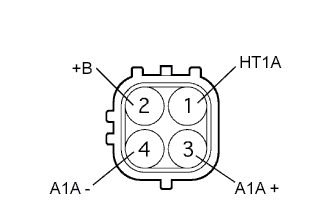
-
Disconnect the A18 sensor connector.
-
Measure the resistance of the sensor.
Standard resistance Tester Connection Condition Specified Condition 1 (HT1A) - 2 (+B) 20°C (68°F) 1.8 to 3.4 Ω 1 (HT1A) - 4 (A1A-) Always 10 kΩ or higher
NG
REPLACE AIR FUEL RATIO SENSOR
OK
-
-
INSPECT A/F RELAY (Marking: A/F)
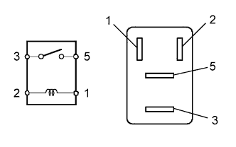
-
Remove the A/F relay from the engine room relay block.
-
Measure the resistance of the relay.
Standard resistance Tester Connection Specified Condition 3 - 5 10 kΩ or higher 3 - 5 Below 1Ω
(when battery voltage is applied to terminals 1 and 2)
NG
REPLACE A/F RELAY
OK
-
-
CHECK WIRE HARNESS (A/F SENSOR - ECM)
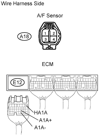
-
Disconnect the A18 A/F sensor connector.
-
Disconnect the E12 ECM connector.
-
Measure the resistance of the wire harness side connectors.
Standard resistance Tester Connection Specified Condition A18-1 (HT1A) - E12-1 (HA1A) Below 1 Ω A18-3 (A1A+) - E12-21 (A1A+) Below 1 Ω A18-4 (A1A-) - E12-31 (A1A-) Below 1 Ω A18-1 (HT1A) or E12-1 (HA1A) - Body ground 10 kΩ or higher A18-3 (A1A+) or E12-21 (A1A+) - Body ground 10 kΩ or higher A18-4 (A1A-) or E12-31 (A1A-) - Body ground 10 kΩ or higher 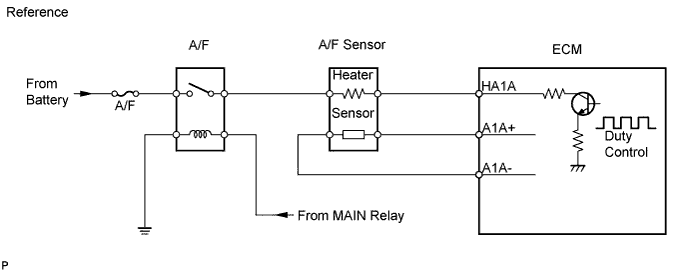
NG
REPAIR OR REPLACE HARNESS AND CONNECTOR
OK
-
-
CHECK AIR INDUCTION SYSTEM
-
Check for vacuum leaks in the air induction system.
OK No leaks in the air induction system.
NG
REPAIR OR REPLACE AIR INDUCTION SYSTEM
OK
-
-
CHECK FUEL PRESSURE
-
Check the fuel pressure (high or low fuel pressure) Click here.
NG
REPAIR OR REPLACE FUEL SYSTEM
OK
-
-
INSPECT FUEL INJECTOR ASSEMBLY
-
Check the injector injection (high or low fuel pressure) Click here.
NG
REPLACE FUEL INJECTOR ASSEMBLY
OK
-
-
REPLACE AIR FUEL RATIO SENSOR
NEXT
-
PERFORM CONFIRMATION DRIVING PATTERN
Tech Tips
Clear all DTCs prior to performing the confirmation driving pattern.
NEXT
-
CHECK IF DTC OUTPUT RECURS
-
Connect the intelligent tester to the DLC3.
-
Turn the ignition switch ON and turn the intelligent tester ON.
-
Select the following menu items: Powertrain / Engine and ECT / DTC.
-
Read DTCs.
Result Display (DTC Output) Proceed to No output A A/F sensor circuit DTCs B
B
REPLACE ECM AND PERFORM CONFIRMATION DRIVING PATTERN
A
-
-
CONFIRM IF VEHICLE HAS RUN OUT OF FUEL IN PAST
YES The vehicle has run out of fuel in the past.
NO
CHECK FOR INTERMITTENT PROBLEMS
YES 
DTCS ARE CAUSED BY RUNNING OUT OF FUEL
-
PERFORM CONFIRMATION DRIVING PATTERN
Tech Tips
Clear all DTCs prior to performing the confirmation driving pattern.
NEXT
-
CHECK IF DTC OUTPUT RECURS
-
Connect the intelligent tester to the DLC3.
-
Turn the ignition switch ON and turn the intelligent tester ON.
-
Select the following menu items: Powertrain / Engine and ECT / DTC.
-
Read DTCs.
Result Display (DTC Output) Proceed to A/F sensor circuit DTCs A No output B
B
CONFIRM IF VEHICLE HAS RUN OUT OF FUEL IN PAST Click here
A
-
-
REPLACE AIR FUEL RATIO SENSOR
NEXT
-
PERFORM CONFIRMATION DRIVING PATTERN
Tech Tips
Clear all DTCs prior to performing the confirmation driving pattern.
NEXT
-
CHECK IF DTC OUTPUT RECURS
-
Connect the intelligent tester to the DLC3.
-
Turn the ignition switch ON and turn the intelligent tester ON.
-
Select the following menu items: Powertrain / Engine and ECT / DTC.
-
Read DTCs.
Result Display (DTC Output) Proceed to No output A A/F sensor circuit DTCs B
B
REPLACE ECM AND PERFORM CONFIRMATION DRIVING PATTERN
A
-
-
CONFIRM IF VEHICLE HAS RUN OUT OF FUEL IN PAST
YES The vehicle has run out of fuel in the past.
NO
CHECK FOR INTERMITTENT PROBLEMS
YES
DTCS ARE CAUSED BY RUNNING OUT OF FUEL