DYNAMIC RADAR CRUISE CONTROL SYSTEM Distance Control Switch Circuit
| DTC Code | DTC Name |
|---|---|
| Distance Control Switch Circuit |
DESCRIPTION
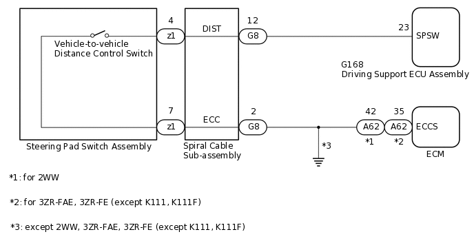
The vehicle-to-vehicle distance control switch is used to set the distance for vehicle-to-vehicle distance control mode. The vehicle-to-vehicle distance control switch is installed in the steering pad switch assembly. The vehicle-to-vehicle distance set value can be changed by operating the vehicle-to-vehicle distance control switch (steering pad switch assembly) while the dynamic radar cruise control system is controlling vehicle speed in vehicle-to-vehicle distance control mode.
WIRING DIAGRAM
PROCEDURE
READ VALUE USING GTS (DISTANCE CONTROL SWITCH)
Connect the GTS to the DLC3.
Turn the ignition switch to ON.
Turn the GTS on.
Enter the following menus: Powertrain / Radar Cruise2 / Data List.
Check the Data List to confirm function of the distance control switch.
Powertrain > Radar Cruise2 > Data List
Tester Display
Measurement Item
Range
Normal Condition
Diagnostic Note
Distance Control Switch
Distance control switch signal
ON or OFF
ON: Distance control switch on
OFF: Distance control switch off
-
Powertrain > Radar Cruise2 > Data List
Tester Display
Distance Control Switch
OK
The display changes in accordance with switch operation.
Result
Proceed to
OK
NG
INSPECT STEERING PAD SWITCH ASSEMBLY
Remove the steering pad switch assembly.
Inspect the steering pad switch assembly.
Result
Proceed to
OK
NG
INSPECT SPIRAL CABLE SUB-ASSEMBLY
Remove the spiral cable sub-assembly.
for Single Type:Click here
for Dual Type:Click here
Inspect the spiral cable sub-assembly.
for Single Type:Click here
for Dual Type:Click here
Result
Proceed to
OK
NG
CHECK HARNESS AND CONNECTOR (SPIRAL CABLE SUB-ASSEMBLY - DRIVING SUPPORT ECU ASSEMBLY)
for 2WW:
Disconnect the G8 spiral cable sub-assembly connector.
Disconnect the G168 driving support ECU assembly connector.
Disconnect the A62 ECM connector.
Measure the resistance according to the value(s) in the table below.
Standard Resistance
Tester Connection
Condition
Specified Condition
G8-12 (DIST) - G168-23 (SPSW)
Always
Below 1 Ω
G8-12 (DIST) or G168-23 (SPSW) - Body ground
Always
10 kΩ or higher
G8-2 (ECC) - A62-42 (ECCS)
Always
Below 1 Ω
for 3ZR-FAE, 3ZR-FE (except K111, K111F):
Disconnect the G8 spiral cable sub-assembly connector.
Disconnect the G168 driving support ECU assembly connector.
Disconnect the A62 ECM connector.
Measure the resistance according to the value(s) in the table below.
Standard Resistance
Tester Connection
Condition
Specified Condition
G8-12 (DIST) - G168-23 (SPSW)
Always
Below 1 Ω
G8-12 (DIST) or G168-23 (SPSW) - Body ground
Always
10 kΩ or higher
G8-2 (ECC) - A62-35 (ECCS)
Always
Below 1 Ω
except 2WW, 3ZR-FAE, 3ZR-FE (except K111, K111F):
Disconnect the G8 spiral cable sub-assembly connector.
Disconnect the G168 driving support ECU assembly connector.
Measure the resistance according to the value(s) in the table below.
Standard Resistance
Tester Connection
Condition
Specified Condition
G8-12 (DIST) - G168-23 (SPSW)
Always
Below 1 Ω
G8-12 (DIST) or G168-23 (SPSW) - Body ground
Always
10 kΩ or higher
G8-2 (ECC) - Body ground
Always
Below 1 Ω
Result
Proceed to
OK
NG
NG REPAIR OR REPLACE HARNESS OR CONNECTOR