WIPER AND WASHER SYSTEM(w/ Rain Sensor) TERMINALS OF ECU
CHECK WINDSHIELD WIPER RELAY ASSEMBLY
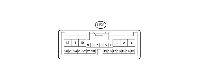
Disconnect the H56 relay connector.
Measure the voltage and resistance according to the value(s) in the table below.
Terminal No. (Symbol)
Wiring Color
Terminal Description
Condition
Specified Condition
H56-25 (W) - Body ground
W - Body ground
Front washer switch signal
Front washer switch on
Below 1 Ω
Front washer switch off
10 kΩ or higher
H56-8 (VR2) - H56-21 (VR1)
Y - G
Adjusting ring signal
Windshield wiper switch adjusting ring* changed from (+) side to (-) side
Below 10 to 2700 Ω
H56-2 (IG) - Body ground
L - Body ground
Power source
Ignition switch ON
11 to 14 V
Ignition switch off
Below 1 V
H56-12 (E) - Body ground
BR - Body ground
Ground
Always
Below 1 Ω
Tip:*: The rain sensor sensitivity can be adjusted by the windshield wiper switch assembly adjusting ring.
If the result is not as specified, there may be a malfunction on the wire harness side.
Reconnect the H56 relay connector.
Measure the voltage according to the value(s) in the table below.
Terminal No. (Symbol)
Wiring Color
Terminal Description
Condition
Specified Condition
H56-10 (+1) - Body ground
G - Body ground
Front wiper motor LO speed signal
Front wiper motor in LO operation
11 to 14 V
Front wiper motor off
Below 1 V
H56-11 (+2) - Body ground
GR - Body ground
Front wiper motor HI speed signal
Front wiper motor in HI operation
11 to 14 V
Front wiper motor off
Below 1 V
H56-25 (W) - Body ground
W - Body ground
Front washer motor signal
Front washer switch on
Below 1 V
Front washer switch off
11 to 14 V
H56-1 (+SM) - Body ground
G - Body ground
Front wiper motor operation signal
Front wiper motor in LO or HI operation
11 to 14 V
Front wiper motor off
Below 1 V
H56-3 (C1) - H56-15 (CO)
BE - L
IG signal
Ignition switch ON
11 to 14 V
Ignition switch off
Below 1 V
H56-13 (SIG) - H56-7 (ES)
P - LG
Power source
Ignition switch ON
11 to 14 V
Ignition switch off
Below 1 V
If the result is not as specified, the windshield wiper relay may have a malfunction.
CHECK MAIN BODY ECU (INSTRUMENT PANEL JUNCTION BLOCK ASSEMBLY)
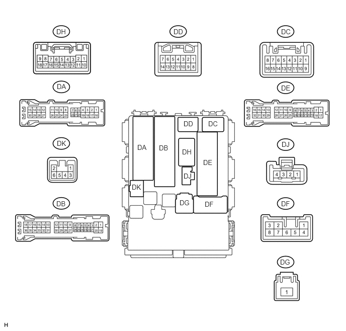
Disconnect the DB, DE, DF, DG and H80 ECU connectors.
Measure the resistance and voltage according to the value(s) in the table below.
Terminal No. (Symbol)
Wiring Color
Terminal Description
Condition
Specified Condition
DB-30 (BECU) - Body ground
W - Body ground
ECU power supply (from battery)
Always
11 to 14 V
DG-1 (IG) - Body ground
W - Body ground
IG signal
Ignition switch off
Below 1 V
Ignition switch ON
11 to 14 V
DF-5 (ACC) - Body ground
W - Body ground
ACC signal
Ignition switch off
Below 1 V
Ignition switch ACC
11 to 14 V
DE-28 (GND1) - Body ground
W-B - Body ground
Ground
Always
Below 1 Ω
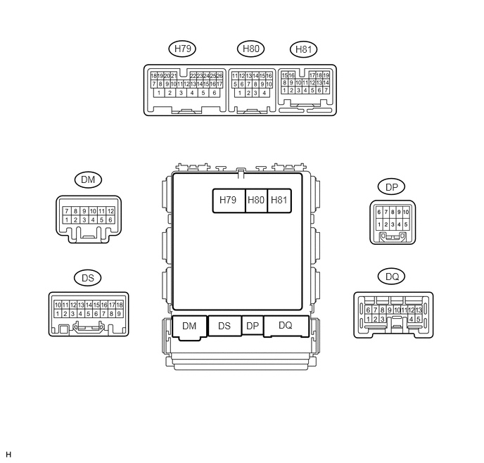
H80-4 (GND2) - Body ground
W-B - Body ground
Ground
Always
Below 1 Ω
If the result is not as specified, there may be a malfunction on the wire harness side.
Reconnect the DB, DE, DF, DG and H80 ECU connectors.
Measure the voltage according to the value(s) in the table below.
Terminal No. (Symbol)
Wiring Color
Terminal Description
Condition
Specified Condition
H81-19 (HDLO) - Body ground*1, *2
G - Body ground
Low beam headlight operation signal
Low beam headlights not operating
Below 1 V
Low beam headlights operating
11 to 14 V
H79-20 (HRLY) - Body ground*2
B - Body ground
Headlight cleaner switch operation signal
Headlight cleaner switch off
11 to 14 V
Headlight cleaner switch on
Below 1 V
*1: for HID Headlight
*2: w/ Headlight Cleaner System
If the result is not as specified, the ECU may have a malfunction.
CHECK HEADLIGHT CLEANER CONTROL RELAY(w/ Headlight Cleaner System)

Disconnect the A67 relay connector.
Measure the resistance and voltage according to the value(s) in the table below.
Terminal No. (Symbol)
Wiring Color
Terminal Description
Condition
Specified Condition
A67-3 (IG) - Body ground
G - Body ground
IG signal
Ignition switch off
Below 1 V
Ignition switch ON
11 to 14 V
A67-4 (E) - Body ground
W-B - Body ground
Ground
Always
Below 1 Ω
A67-1 (HDLO) - Body ground*
SB - Body ground
Low beam headlight operation signal
Low beam headlights not operating
Below 1 V
Low beam headlights operating
11 to 14 V
A67-2 (H) - Body ground
R - Body ground
Headlight cleaner switch operation signal
Headlight cleaner switch on
11 to 14 V
Headlight cleaner switch off
Below 1 V
A67-6 (PB) - Body ground
B - Body ground
Headlight cleaner motor signal
Always
11 to 14 V
A67-5 (FRWA) - Body ground*
W - Body ground
Front washer motor operation signal
Front washer switch off
11 to 14 V
Front washer switch on
Below 1 V
*: for HID Headlight
If the result is not as specified, there may be a malfunction on the wire harness side.